
Our first article in this series highlighted some bandwidth demand drivers and introductory standards information. This article will focus on critical optical parameters starting with optical attenuation. Additional articles in this series focus on other optical parameters, including chromatic and polarization mode dispersion, splice loss, and an introduction to non-linear effects.
There are three main loss mechanisms in fibers, and we’ll briefly discuss each. Those Attenuation mechanisms are:
- Scattering
- Absorption
- Bending
Scattering
The first mechanism is “Rayleigh scattering” of light in fiber. This mechanism contributes most to the baseline attenuation of fiber. A certain amount of light is scattered in the glass. In the simplest of terms, scattered light is simply light that is no longer guided through the optical fiber, but instead propagates in some other random direction (an interesting side note is that OTDRs measure loss by using the light that is scattered backwards in a fiber so the device only needs to be connected to one end of the optical fiber). Since some light doesn’t transmit forward through the glass, loss occurs. The classic attenuation curve has a relationship of attenuation proportional to 1/λ4 and is driven by the properties of Rayleigh scattering. Rayleigh scattering is the result of small fluctuations of glass density in an optical fiber and is the same mechanism responsible for the blue color of the sky, when sunlight scatters off molecules in the atmosphere.
The scattering-related attenuation properties of the glass are determined by the materials used in the glass, and are frozen in during fiber manufacturing.
Absorption Attenuation
Impurities may absorb or reflect light. This is why fiber manufacturers pay such close attention to the quality of materials used in the glass and to cleanliness during manufacturing. Particles as small as a fraction of a micron can be large enough to absorb enough light to increase loss.
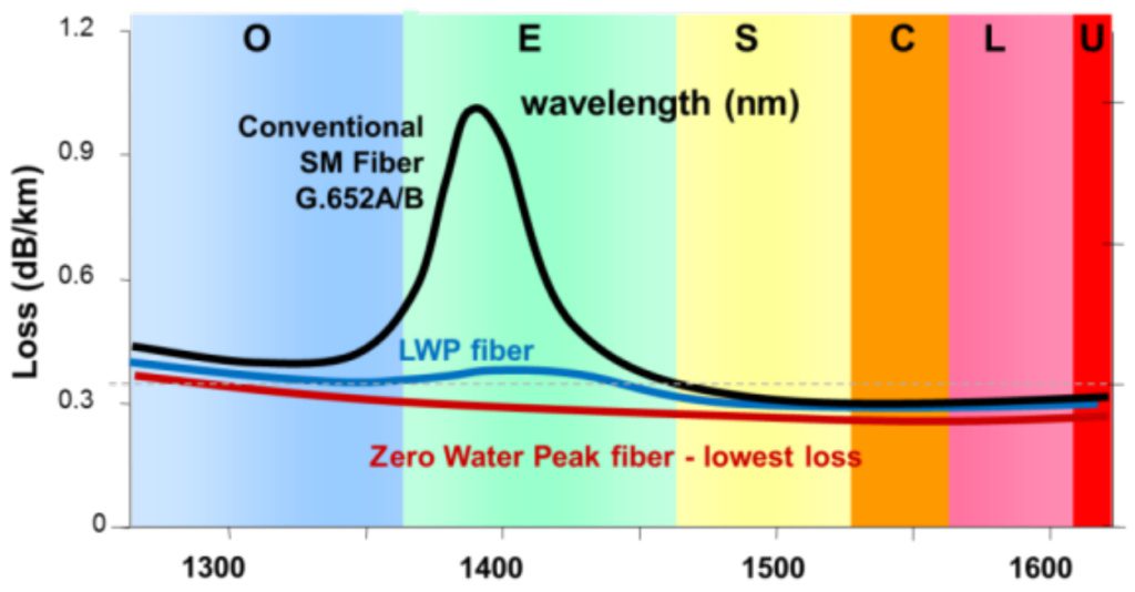
Besides particles, impurities in the raw materials used in the fiber manufacturing process itself can increase loss. That’s because the hydroxyl (OH) ion is a by-product of the manufacturing process. It absorbs light in the wavelength range around 1383 nm.
The graph to the right shows the loss performance across the wavelength range with three different grades of fiber.
Bending
Bending is a very important mechanism. The cabling process and installation in the field can affect attenuation caused by bending.
Let’s go back to Fiber 101. Fibers use the concept of total internal reflection to guide light. The refractive index profile of the core and the cladding determine how light is guided, and the term “critical angle” is used to describe when reflection turns to refraction and light is lost from the fiber. In short, when fiber is bent tightly, light can be lost.
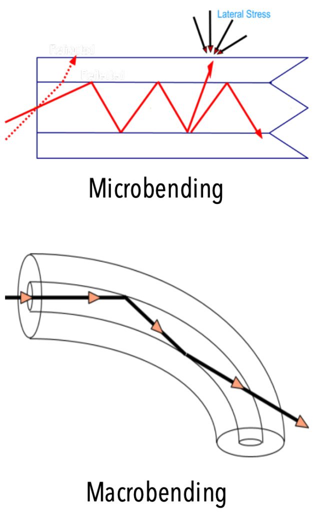
There are two main modes of bending – macrobending and microbending.
While the end result of both types of bending is attenuation, the mechanisms and how they manifest differ.
> For more details, Download the Full Article
Other Ways Microbends and Macrobends Show Up in the Network
The concepts of micro and macro bends affect the network in ways that are not always obvious.
Bend-related loss is also sometimes experienced in cold temperature environments. For this reason, fiber and cable qualifications should always include tests to see how products perform in cold temperatures. As a network designer, it’s always a good idea to account for at least some optical margin for small potential attenuation increases in cold temperatures.
Help is On the Way
The good news is that fiber manufacturers have developed fibers that can withstand different amounts of bending while also reducing loss compared with traditional fibers meeting the ITU G.652.D Recommendation. These fibers are called bend insensitive or bend optimized fibers, and are defined by ITU Recommendation G.657.
For the network designer and installer, a thorough understanding of various attenuation mechanisms can assist with the network planning and installation processes, enabling proper loss budgeting and the use of appropriate products for the application.
In most situations, attenuation is the most important network parameter, and this article has provided enough background for you to be well on your way to fiber geekdom on this topic. However, fiber geekdom is a journey, not a destination, and there’s always more to learn. OFS has multiple decades of experience with fiber optic networks. Please contact your local OFS representative if you would like additional information regarding any of the items in this article.
> Download the Article for full details.
About the Author:

Mark Boxer is Technical Manager, Solutions and Applications Engineering for OFS. In this role, he assists customers deploying fiber in a wide variety of network design scenarios around the world and analyzes trends in telecommunications markets that drive new product innovation. Mark has a BME degree from Georgia Tech, and has spent his 30+ year career in the fiber industry. His experience includes varied roles in manufacturing and applications engineering for fiber-based products and markets. Other activities include inventor of six US Patents, member and past Secretary of the IEEE Power Engineering Society Fiber Optic Working Group, contributing member to the Fiber Broadband Association (FBA) (formerly FTTH Council) Technology Committee and Board of Directors member of the FBA.
Tags: attenuation, optical fiber properties , Rayleigh scattering