We use cookies to help us provide you with a more enhanced and personalized experience adapted to your interests. By using our site you agree to our Terms of Use and Privacy Policy, including our use of cookies.
OFS AcoustiSens® Optical Fibers used in random OPO system demonstration
By Regina Pynn, OFS Industrial Sensing & Networking Market Manager
Once again, OFS optical fibers are paving the way for researchers to bring cutting-edge technology out of the lab and into practical applications. This time, we’re delving into the realm of optical fiber sensing – a technology that relies on a carefully tuned light source with specific traits like wavelength, power, and pulse width.
Generally optical fiber sensing starts with a laser, but they come with a catch: lasers have their materials carefully selected to emit stable light pulses at a specific desired wavelength, limiting their flexibility. A system with wavelength modulation promises exciting innovations for fields as diverse as quantum computing and LiDAR sensing.
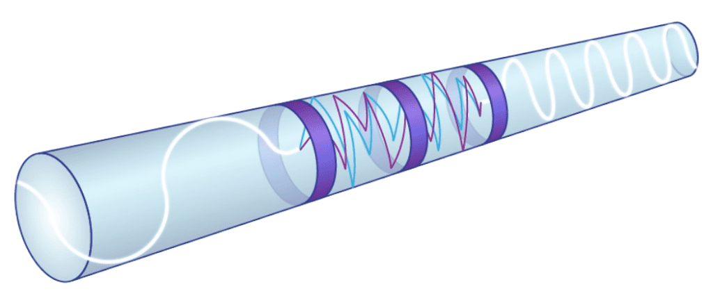
OPOs can use the deliberate scattering in AcoustiSens optical fiber to change the wavelength of light pulses
Enter the optical parametric oscillator (OPO). It transforms regular laser light into controlled wavelength pulses by guiding the laser light into an optical cavity, bouncing it around nonlinear crystals and resonators. As the light moves through the cavity and is sent back over itself multiple times the system changes wavelengths and creates parametric amplification.
However, there’s a hiccup in this dazzling performance: OPOs are quite sensitive to temperature and environmental changes. Even small changes impact the wavelength and power of the light as it exits the cavity, confining OPOs mostly to high-maintenance lab settings.
Researchers theorized that a random laser, which encourages scatter in the light source, would make the system more robust because the scattering would come from the controlled design of the laser and not be at the mercy of environmental changes in the optical cavity.
A groundbreaking paper from the University of Ottawa validates this concept. A team demonstrated, for the first time, that an augmented sensing optical fiber like OFS’ AcoustiSens can make this idea a reality. AcoustiSens is manufactured with enhanced Rayleigh scattering and this scattering allowed the OPO system to have stable, tuned wavelengths in a simple and robust optical cavity.
Congratulations to the University of Ottawa team and to all the technologists working to unshackle OPOs from the lab.
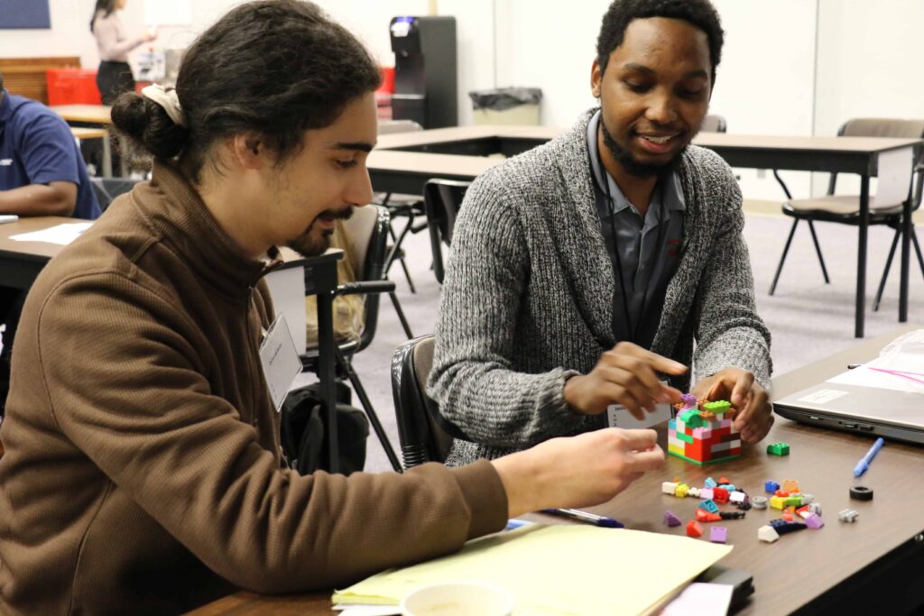
We recently concluded a remarkable event at our global headquarters in Norcross, Georgia – the OFS Early Career Talent Orientation. Over sixty rising talents from diverse corners of the world, including Connecticut, Denmark, Georgia, Massachusetts, and Morocco, New Jersey, and the United Kingdom gathered for an immersive experience that went beyond the conventional boundaries of onboarding.
At OFS, we believe in investing in our people, recognizing that their growth fuels the growth of our company. The orientation was crafted to be more than just an introduction to our facilities; it was a dynamic blend of learning, networking, and exposure to different facets of our business globally.
Building the Leaders of Tomorrow:
Our primary goal for this initiative was clear – to develop and prepare the next level of leaders within our organization. Through a series of engaging sessions, participants were equipped with the knowledge and skills essential for their roles. The event underscored our commitment to fostering a diverse talent pool, ensuring that every individual feels valued and empowered.
Connecting Cultures, Igniting Innovation:
One of the key takeaways from the orientation was the emphasis on global opportunities. Our company’s growth translates into personal growth for each employee, making the journey truly fulfilling. Participants discovered that subject matter expertise extends beyond their immediate roles; it involves understanding how people from different backgrounds approach challenges. Cultural sensitivity was not just a talking point; it was a lived experience, recognizing its increasing importance in our interconnected world.
Mission-Driven, Values-Led:
The presentations during the orientation reiterated our mission and values, serving as guiding principles for every OFS team member. Our commitment to building a sustainable enterprise that benefits the community, provides a great workplace for our employees, and remains the first choice for our customers was at the forefront of discussions.
OFS Safety Policy: Our Priority, Your Assurance:
As part of our commitment to our employees’ well-being, we also emphasized the importance of the OFS safety policy. Ensuring a safe working environment is not just a mandate but a promise we uphold, creating a workplace where everyone can thrive.
Mentorship:
OFS actively engages in mentorship for all employees. We share wisdom across the organization to enable all our employees to deliver their best work. Senior leaders spend time preparing the next level of leadership for the future of our global business. The partnerships and shared learning experiences are unique features of how OFS demonstrates inclusivity.
Looking Ahead:
The Early Career Talent Orientation was not just an event; it was a cornerstone in the journey of each participant and the collective growth of OFS. We are excited about the positive impact it will have on our company as these talented individuals bring their newfound knowledge, perspectives, and enthusiasm to their roles.
We are not just building a workforce; we are nurturing a community of global leaders who will play a pivotal role in shaping the future of OFS. We extend our gratitude to everyone who contributed to the success of this event, and we eagerly anticipate the continued growth and success of our newly onboarded team members.
Employee Perspectives
Insights into Working at OFS
Gain an authentic understanding of life at OFS. Get a firsthand look into the vibrant, collaborative, and inspiring environment that awaits you. We invite you to explore our culture, connect with our employees, and envision yourself as part of the OFS family.
Dual-Brillouin-Peak Optical Fiber was designed and fabricated by researchers from OFS
In an era of advanced sensing technologies, the dual-Brillouin-peak optical fiber emerges as a new practical solution forresolving the strain-temperature cross-sensitivity that exists in almost all optical fiber sensors. Its potential spans across a multitude of fields, demanding precision over long distances and high resolutions. This groundbreaking technology is set to redefine the boundaries of Brillouin scattering based distributed fiber sensing.
Dual-Brillouin-peak single-mode optical fiber can measure both strain and temperature at the same time. This is a very useful feature for applications such as structural health monitoring, oil and gas exploration, and power transmission.
Dual-Brillouin-peak single-mode optical fiber has two distinct peaks in its Brillouin gain spectrum with similar amplitude levels. By measuring the frequency shifts of these two peaks, we can determine both the strain and the temperature along the fiber.
This is different from conventional single-mode optical fibers, which have only one dominant Brillouin peak and can only measure either strain or temperature, but not both at the same time. To measure both parameters, we would need to use two different fibers or a special fiber with a coating that has a different thermal expansion coefficient that usually results in an ill-conditioned discrimination.
The dual-Brillouin-peak optical fiber has several advantages over these methods. First, it simplifies the measurement system by reducing the number of components and connections. Second, it eliminates the need for calibration or compensation of the thermal expansion coefficient. Third, it increases the accuracy and resolution of the measurements by enhancing the Brillouin gain of the higher-order acoustic mode.
The researchers demonstrated the performance of their optical fiber in a 25-kilometer sensing length with 5-meter spatial resolution. They achieved a temperature resolution of 2°C and a strain resolution of 40 microstrain.
The fiber and standard single-mode telecom fibers are interchangeable with low splicing loss. The fiber is fully compatible with existing BOTDR/BOTDA (Brillouin Optical Time Domain Reflectometer/Analyzer) interrogators in the market. The dual-Brillouin-peak optical fiber is a promising technology for simultaneous distributed strain and temperature measurement. It has potential applications in various fields that require long-distance and high-resolution sensing.
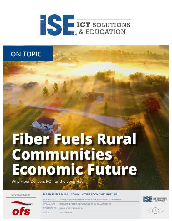
With the $42.5 billion Broadband Equity, Access, and Deployment (BEAD) state allocations announced on June 26, states are now proactively creating plans to build high speed broadband networks to the unserved and underserved – all the way down to the last home or business on the farthest dirt road of every community.
In this On Topic, you’ll get a deep look at the critical impact fiber is making in rural communities. You’ll see how providers are able to make such a profound difference in these economies, as well as the technical “how-to” that makes these accomplishments possible.
Hi, I’m Mark Boxer, Technical Manager with OFS, and here’s what’s new in my world.
The first waves of fiber deployments were focused on single family homes and for good reason. There wasn’t as much demand for bandwidth and MDU or multi dwelling units and 15 to 20 years ago we just really didn’t have the same products that are now routinely used in MDUs. You know MDUs 15-20 years ago were some expensive science projects. So much has changed and it really can now make sense to do MDUs first.
So, first, broadband demand rises in single family homes and MDUs, and the commercial and regulatory environments are also changing. And very importantly the industry has responded with new products and installation methods that dramatically simplify the installation process and then to use. So as an industry we’ve learned that fiber installations and MDUs need to be fast, easy, and not visible – to preserve the building decor. The fiber also needs to be able to withstand the many bends of an apartment. InvisiLight Solutions enable these types of installations.
We’ve also discovered that with these tools, fiber installations for MDUs really have now flipped the script so these solutions are fast. They’re easy and inexpensive to install, meaning these installations can also be very profitable for network operators to deploy.
At a time when outside plant cable lead times may be long, indoor fiber products may have shorter lead times, which means that service could be turned up more quickly. We’ve also discovered that with these tools, the products can be installed with the minimal amount of training. A crew can be up and running within minutes to hours. Or, as we’ve heard people say before, on Thursday he’s a taxi driver, on Friday he’s an InvisiLight installer.
It can make sense for a service provider to consider MDUs first. So, let’s take a closer look. The Ultra bend insensitive fiber standard that’s used in these builds is G.657B3 and the OFS brand name for this fiber type is EZ-Bend fiber. You can bunch it up and tie it into knots. You can run into very tight angles and staple it with little added loss.
Many MDUs have lots of bends, and if you use a typical outside plant cable to do what I just did with the knot, then that would turn out the lights. However, we routinely deploy EZ-Bend and InvisiLight in environments with dozens of 90-degree angles, with no issues.
So, I was on a MDU build a couple of weeks ago where we went through forty-five 90-degree angles, two splices, and two connectors. The result was a loss of less than half a DB from the splitter to the ONT, and frankly that’s impressive.
The term InvisiLight is a nod to the light that goes into the fiber and the fact that it’s also almost invisible to the resident. Out of sight, out of mind. These products are deployed in minutes.
Deploying to MDUs can be fast and inexpensive to deploy, inconspicuous with low optical loss, and reasonably available supply chain. When you add these benefits together, it’s worth considering MDUs first. That’s what’s new in my world.
Visit our step-by-step Invisilight MDU/ILU product configurator for starting a Bill of Materials for your building.
This configurator is designed for buildings with riser spaces and indoor hallways. Additional options are available.
Hi, I’m John George, Senior Director of Solutions Engineering and Fusion Splicers at OFS. What’s new in my world is our new MDU!Click® Solution for fiber deployment in buildings.
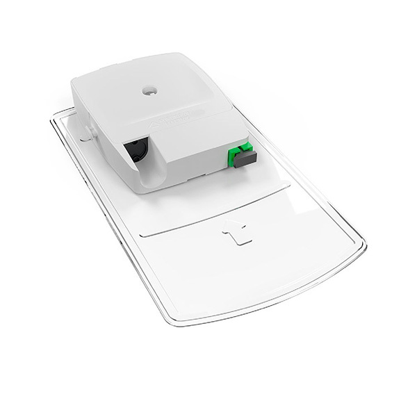
With the MDU!Click Solution we can defer the cost of a splitter module until we have a higher take rate on each floor. This is for a pay-as-you-grow kind of deployment. It’s used for a second, or third entrant into the building, fiber to the business deployments, or maybe high take rates aren’t expected initially and there’s a desire to defer the cost of the build as much as possible with subscriber growth.
The way the system works is we have a MDU!Click SlimBox® Flex Indoor Module in the MDF the entry point of the building with a one by four or one by eight splitter feeding through the EZ-Bend® 12 or 24 fiber riser cable. You can see this is a very compact cable that can fit in limited spaces. We’re breaking out a single fiber so we can support one subscriber per floor in the initial deployment. Then, we can connect that first subscriber by plugging in one of our EZ-Bend Jumpers – a drop cable assembly that can go many hundreds of feet if needed.
The EZ Bend cable has a 2.5 millimeter bend radius to handle the cornering in the buildings that’s often required. Then, to add more than one subscriber on each floor, we simply put in place our MDU!Click SlimBox Flex Indoor Splitter Module and expand from one to eight ports. We can reconnect our initial subscriber and connect seven more subscribers on that floor, in order to get a higher take rate as we get new subscribers in the building.
That’s what’s new in my world, the MDU!Click® Solution for fiber in the building.
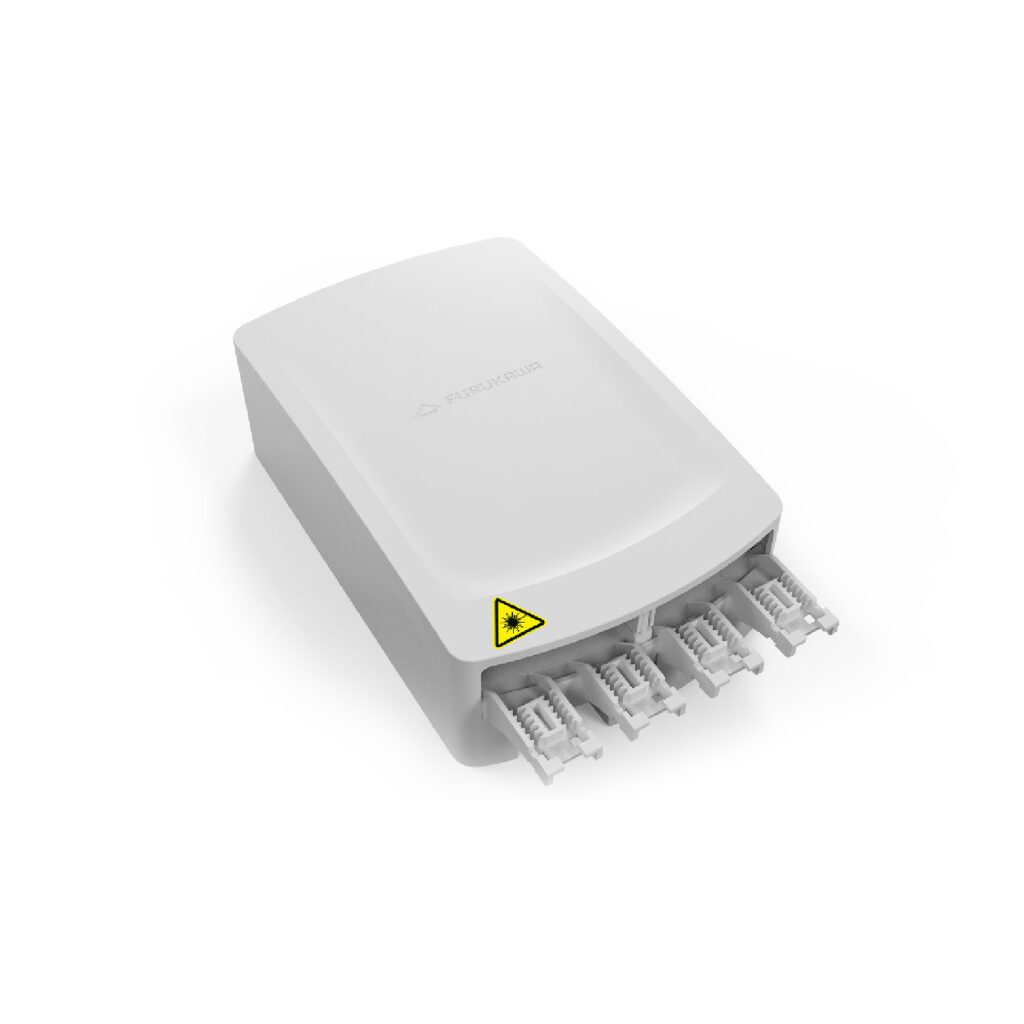
HCS® Industrial Graded-Index and Step-Index Fiber Optic Cable Selection Guide
Indoor and outdoor optical fiber cables for use in Substation Automation, Factory Automation, Industrial Ethernet, HVDC Systems, and Power Electronics.
When you’re trying to decide on which fiber optic cable to choose for an application. You have many choices of various constructions and fiber types of as has made this step easier for you. With the help of our new cable selection guide, which consists of cables for industrial applications, what the selection guide is designed to do is to make your job easier to determine the most appropriate and cost-effective cable for your project or installation. The selection guide is going to focus on the office industrial multimode fiber optic cables that are designed for, and common in, many factories and substations, as well as other harsh environment applications.
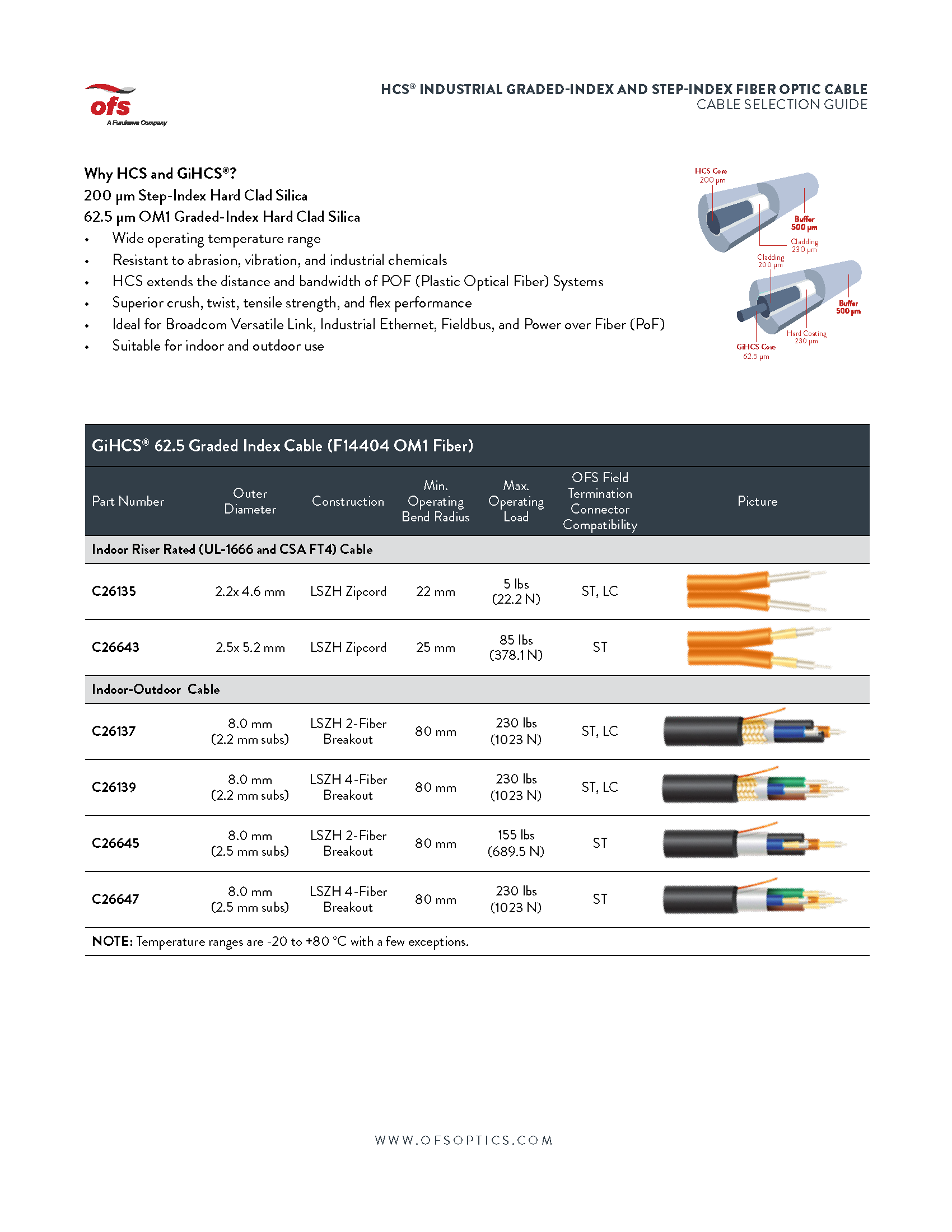
For those of you who work in industrial environments, whether it be a steel mill, paper mill, a substation, or any type of harsh environment, the HCS product line is ideal for you for many reasons. Unlike traditional fibers, the primary fiber coating makes bonds to the fiber and enhances the strength during the draw or production process. Additionally, because the coating remains on the glass during the termination process, the fiber maintains its inherent strength. This makes it unique in that there is never bare glass exposed to the environment such as humidity, dirt, and dust. Those environmental factors are all known to detract from the strength of the fiber optics. When you’re considering the product line, here’s what you’re getting a rugged and robust construction resistance to abrasion in industrial chemicals. Reliable and repeatable termination process. A short learning curve for terminations. So selection considerations include extreme temperatures of Florida, Arizona, to the frigid temperatures of the Canadian tundra or Alaska. Humidity also plays a factor in states like Texas and Louisiana. You will also consider installation pull strength, the compressive strength of the cable. What kind of weight can the cable bear during the installation?
The first page here we have 62.5 micron cables, which are indoor zipcord cables for data center type applications. Indoor outdoor cables which can be used for either these are breakout cables and all the outdoor cables will have a water block in the cable as well as some of them will have a glass armor for road and deterring because you’re going to deter the road they’re trying to chew through the cable.
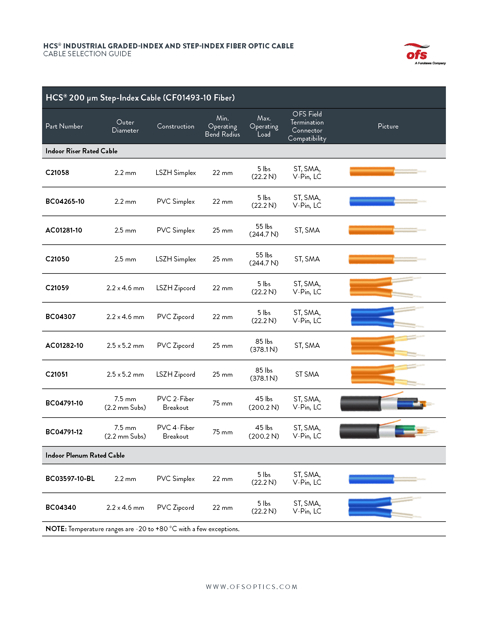
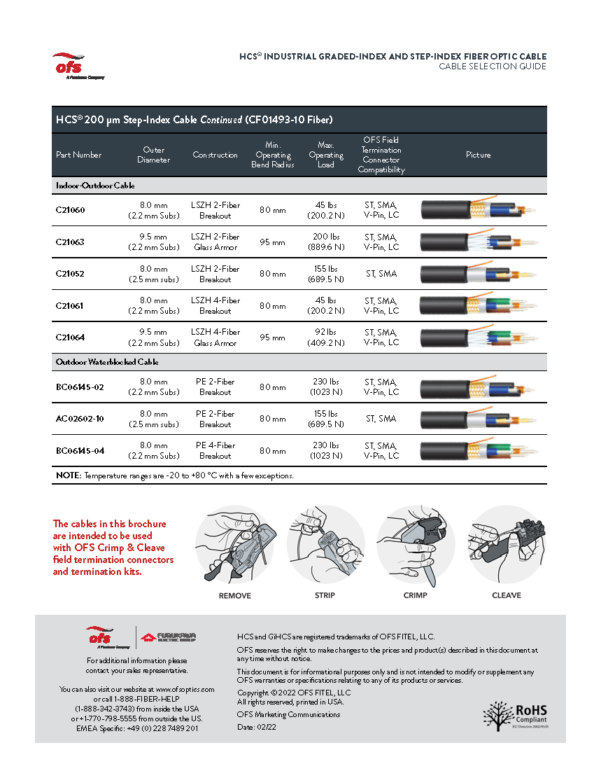
And looking at our 200 micron step index cable from simplex to zip cords to breakouts through indoor applications, we have riser rated we have plenum rated, we have indoor outdoor cables. And we also have cables that are designed strictly for outdoor applications. Again, with the water block, as you see at the bottom here, we have a schematic which shows the termination process of a typical O of this connector.
First, we’re going to remove the cable jacket, then we’re going to strip the fiber. Then we’re going to crimp the connector on, and then we’re going to cleave the glass. And for a pristine finish on the end of the connector. What I’ll do in my next talk is share with you information on the connector systems that go along with the cables we just talked about. And that’s what’s new in my world.
Mark Boxer, OFS Technical Manager, reveals what makes Rollable Ribbon so special. To form these ribbons, fibers are partially bonded to each other at intermittent points. This design not only enables mass fusion ribbon splicing but allows for easier individual fiber breakout than flat ribbons. The preferential bending plane of the rollable ribbons facilitates rolling and routing in smaller closures and splice trays, similar to individual fibers.
Hi. I’m Mark Boxer with OFS. Today I’d like to talk about Rollable Ribbon and if you haven’t seen it before, it is this stuff, so it’s pretty neat. It collapses upon itself when it’s rolled into a tight cylinder so you can kind of collapse it.
And then you can also easily separate it out to pull out an individual fiber. So, I’ll do that and get a little bit closer. So you can see that and then it just snaps back into place so you can slice it again. So, it splices like a ribbon. It can be rolled very, very tightly, providing the ability of tight fiber density in a very, very small package.
So, you compare this to a flat ribbon. This is a flat ribbon and so there is no there is no moving of this or no rolling this without breaking the ribbon. So why this is important really comes back to geometry. So, this is an 864 fiber central to flat ribbon cable. So, if you look at it, you can see that there is a lot of space in between the flat ribbons and the tube.
And that’s because we’ve got ribbons that are fundamentally rectangles. And the cable is fundamentally a circle. When you have a circle and a rectangle, then it those don’t fit that efficiently. If you look at a rollable version of this cable with 864 fibers, you can see here there’s not very much space between the fibers and the tube.
And let me go ahead and put both of these side by side. And you can see that this is the flat ribbon 864. This is the rollable 864. Now there’s a significant difference in size between the two.
Rollable Ribbon was dreamed up in Japan back in the 2000’s and went through a development path that was actually similar to the SC Connector that happened in the early 1990s.
And what I mean by that is that NTT in Japan farmed out the concept to various companies who ultimately brought it to market. For the case of Rollable Ribbon OFS parent company, Furukawa was one of those companies that introduced Rollable Ribbon and so we brought it back to brought it to market during the middle part of the 2010’s.
So there are so many benefits to Rollable Ribbon. You know, we see it in a lot of different environments, and I call this the buffet of benefits using Rollable Ribbon. It’s small. The ribbons themselves are very small so they can be rolled. That means that cables can be much smaller and lighter for a given size.
That can gives the ability to fit more fiber into smaller ducts. It can mean smaller hand holds more cable on a real for longer lengths or fewer slice points. And then for aerial installations also since everything’s smaller, also less weight on the pole, less amount of ice to build up. Smaller in general typically makes things easier. Some customers like it because it can be placed in thinner slice trays enabling more trays and a closure or a smaller closure for a given fiber count.
All of these cables are gel free, so they’re easier to prepare for slicing. And of course, these are ribbon. So there can be mass fusion spliced 12 at a time. The initial installations were primarily used to connect data centers together because data centers use very high fiber count cables, you know, think of 1728s, 3456s.
But what I’m really excited about is the concept of using rollable ribbons in lower fiber count networks. Including fiber to the home, backbone, and distribution networks. For those applications, we have typically used, lose tube cables in the past because it’s easier to pull out an individual fiber to connect a subscriber. But now with Rollable Ribbon, it’s easier to pick out an individual fiber versus a loose tube. The ribbons or clearly marked, the fiber color is always going to be in the same place. You just basically pick out whatever you need.
So now the cables can be smaller, they can be easier to work with in the field. If you compare these so these 288 fiber count cables. The first is a loose tube. It’s actually pretty big. And this is a flat ribbon cable 288.
So now look at the rollable – and so we’ve got a couple of different versions of this but actually the larger rollable you can see that even the larger rollable is much smaller than either the loose tube or the flat ribbon.
All of these cables are GR20 rated. So you have the same rugged, crush, impact, and tinsel performance that we’ve come to rely on for decades. So give Rollable Ribbon some thoughts for your network. Now you can get the benefits of ribbon slicing when you can use it. Or also single fiber access. You can do either one, whenever or where ever you need to.
It can act as a ribbon. It can also act as a single fiber giving you a lot of freedom to use either platform in a much smaller package.
So overall, we think we’re going to see a lot more customers move towards Rollable Ribbon in their fiber to the home distribution networks. And now in the future.
Sandy Oregon located about 30 miles from downtown Portland is blessed with beautiful mountain scenery but unfortunately its great location also leads to challenges when it comes to being connected to the outside world. In 2002 city officials had the vision to start their own internet service provider and offer affordable internet service to its residents. The result was SandyNet. From the beginning it was a huge success. People wanted it. They were hungry for it.
We had been in municipal ISP for quite some time starting off with DSL and wireless and outgrown that technology and so really the only next step for technology was to go to fiber. So, in 2014 SandyNet partnered with OFS to bring high-speed fiber to Sandy’s businesses and residents. They set some specific goals at the time that included deploying a future-proof fiber optic network. Providing all neighborhoods with the same service enabling residents the ability to access videos, e-learning, gaming, and government services, increasing Sandy’s competitiveness to attract new business and offering the city-owned network as a utility. In the years since upgrading to a fiber optic network, how has Sandy done with meeting their goals?
Sandy’s seeing some unprecedented growth right now both on the residential side and a lot of commercial opportunities. Going forward, SandyNet will continue to help lure people here and increase our tax base, increase our residence and increase the virtual learning environment that a lot of our students are partaking in. Right now, over the course of the last six seven years, during that time period I’ve talked to a number of people in Sandy who have moved here to the community and while it wasn’t the sole decision that they made the fact that gigabit fiber was available at their residence in a wired solution was the deciding factor for several people to buy a house in this community.
Our community has just thrived with having that big fat fiber pipe. That’s one of the things for us where we were always struggling with the amount of capacity that our previous internet service providers were giving to us. Now we don’t have that problem anymore. We have over capacity in a sense. We have enough to where people can stream and listen to music while they’re working and we can still get all our work done. We can download the data that we need to get it done in minutes, seconds. Instead of an hour or two, we can upload stuff into our servers, into our clients servers, quickly just all of that greatness that comes with having a really fast internet connection.
It’s a great asset to have our SandyNet charges on the same utility bill that our water and sewer charges are on. It’s an easy one payment a month to have this service that you know is much more affordable than a lot of the other providers that are out both in our area and nationally.
But back in 2014 when SandyNet was deploying fiber to try and make its network future proof no one could have foreseen what fiber would mean to not just the town but the entire world in 2020. There was virtually no one whose life was not affected by the COVID-19 pandemic. Having a high speed fiber optic network became the difference between those who were able to keep pace with the world and those who were left wanting something better. It was amazing that we got our fiber put in place when we did. It was built out to so many homes and had gone in front of hundreds of the homes in Sandy. Those that didn’t initially take it, could get it during that time. There was no rationing. We were in school one day and then everyone was at home the next day. Not just students, but also people working from home.
When you have a strand of fiber going to your house providing gigabit capacity it makes working from home very easy and I think a lot of people have been very happy with the service that they’ve gotten here in Sandy. From council meetings being held virtually, to team meetings, and other department meetings at the administrative level, we were able to continue our operations seamlessly with the help of SandyNet During the pandemic we did see an increase in speed upwards of 25 across our overall traffic patterns. Mostly traffic did increase during the workday. Our network is designed to be able to carry that load.
Once the city of Sandy decided to go all in with fiber who better to turn to than OFS. The industry leading experts at OFS were able to design, engineer, and deploy a network that was easily able to meet all of Sandy’s goals for a robust future-proof network.
OFS is able to combine several products that are designed to work with the gigabit, and 10 gigabit, 25 gigabit fiber. OFS can integrate solutions together to provide a complete turnkey solution for fiber to the home to our customers. We have to thank OFS a lot for SandyNet. We can’t go out and buy a book on how to set up fiber to the home network. Working with people that have been in the industry for 30 some years and having a great team that has worked on fiber the home projects in the past has been great. OFS has done all the heavy lifting. They’ve figured out all the optical budget information and then just provided this seamless solution and high-quality product.
Sandy’s been a fantastic success. We really appreciate all the opportunities from the city of Sandy for OFS. A complete OFS product solution along with the design the engineering, the build has provided the city of Sandy residents with great economic enhancement and quality of life improvement for decades to come. It would be a lot harder to differentiate Sandy from any other city of 12,000 people in Oregon. We still have many things that make us unique, but SandyNet really is the biggest one and I think it will have the most impact on our community over time.
To read the audio transcript for The Last 100 Meters of Fiber to and Into the Home click here.
AN OFS WHITE PAPER: NEW TECHNOLOGIES ENABLE FASTER, EASIER FIBER INSTALLATION INTO HOMES AND MDUs
For immediate access to our exclusive FTTH whitepaper, click here.
EZ-Bend Cabling and InvisiLight Solutions enable fast, easy and accepted fiber deployments to and into MDUs, homes and offices.
Executive Summary
Driven by unprecedented demand for Gigabit and fast emerging 10 Gigabit Broadband, Fiber to the Home (FTTH) deployment is expected to reach record numbers in the coming years. According to iDate, FTTH connections will more than double in Europe over the next six years, while RVA forecasts that FTTH investment in North America will double in the next five years compared to the previous five. In addition to homes, service providers are bringing fiber to the living unit in multiple dwelling units (MDUs) and into commercial and institutional buildings. In all these scenarios, a cost-effective and compact optical network terminal (ONT) is typically placed inside each living unit or office to enable Gigabit or even 10 Gigabit connectivity. However, there are aesthetic and cost challenges to placing fiber inside residences or buildings. While service providers typically prefer to deploy ONTs deep within subscribers’ units with co-located Wi-Fi:
there may be no existing fiber ducts or pathways to the ONT location.
installing new ducts or cutting and patching walls can be very expensive and disruptive.
surface mounting conventional fiber cables can be unsightly and result in optical signal loss when the cables are bent around the many sharp corners on the pathway to the ONT.
wire molding or tape systems to house fiber are typically cost prohibitive, visible. and very slow to install.
Transcript:
Good day, my name is John George. I’m Senior Director of Solutions and Professional Services with OFS. Today I want to share what’s new in my world that could help you build better fiber to the home (FTTH).
Originally, FTTH deployments were fiber to outdoor ONTs on the side of a house. From there, copper typically was used to reach an indoor residential gateway inside the home. Over time we discovered indoor ONTs are smaller, and less expensive. They could be deployed inside the home, co-located with the wi-fi in the center of the building and achieve much better wi-fi coverage. This would reduce the cost, but there had to be a way to get the fiber into the home to that indoor ONT.
For MDU’s and apartment buildings, it evolved from fiber to the building, and trying to use the existing in-building copper to bring the internet service to each living unit. That proved to be insufficient from a bandwidth perspective for MDUs. To support 10 gigabit data rates that are being deployed now, it’s desired by service providers to get fiber into each living unit of an apartment building.
I’ll walk you through some innovative technologies we offer, that help solve those significant problems. The first one is EZ-Bend Cabling Solution. This is a three-millimeter diameter cable. It can have connectors on both ends. It can simply be stapled around any corner, and bends sharply in half with no concern about loss whatsoever. It has a 2.5 millimeter minimum bend radius – that’s twice as tight as anything else you can get on the market. The best from others is only five millimeters.
The EZ-Bend 2.5 millimeter bend radius technology is even more necessary as we move to from gigabit, to 10 gigabit. 10 gigabit use longer wavelengths in the transmission system. Longer wavelengths have much higher bend loss than what’s used for the gigabit. So, cable bends in a 10 gigabit transmission is a bigger challenge, but we solve it with the EZ-Bend. You can literally bend it any way without concern for signal loss.
The next technology we offer is the OFS InvisiLight Solution. It‘s used to solve issues inside the home or apartment. Originally, stapling cables inside the home was acceptable. Now, many customers don’t want to see the fiber at all inside the living unit. The OFS InvisiLight Solution is fiber installed inside an apartment, or home that blends into its environment; nearly invisible to anyone looking directly at it. The OFS InvisiLight Solution gets the fiber deep inside to the ONT. We have connectors on both ends of the InvisiLight spool making it easier to deploy a single part number, that can cover up to 132 feet, getting fiber into a home or an MDU living unit.
We also have a 12 fiber version, and a 16 fiber version for MDU hallways. These editions to go down the hallway and drop off the single fiber InvisiLight into the living unit.
Finally, we have the EZ-Bend Single Family Drop Solution that includes drop cabling, from the pole or pedestal to the home, and into the home. This is a double end connectorized assembly that’s toneable orange and can be laid out as a temporary drop, then buried later. What’s beautiful about this is it has the InvisiLight fiber inside the cable, so you can run this to the house below grade, direct buried, or induct, then wrap the house with it, and then to extend into the home to reach the ONT. All that is needed is to strip the jacketing off and then what you have is the fiber outside going through the wall to the inside where we’ve got the InvisiLight deployed to the ONT. Essentially this is a single piece of glass all the way from the curb, into the home, and into connecting the ONT. Quite simple, one part number, you don’t need a Network Interface Device (NID). You don’t need the time to install the NID. You save dollars if you avoid conduit and the NID by going with the EZ-Bend Single Family Drop Solution to the home into the home straight to the ONT.
That’s what’s new in my world. Thank you for listening.