We use cookies to help us provide you with a more enhanced and personalized experience adapted to your interests. By using our site you agree to our Terms of Use and Privacy Policy, including our use of cookies.
What is IEEE Std 802.3cm-2020, 400 Gb/s over Multimode Fiber?
The work of the IEEE Std P802.3cm Task Force was approved as a new standard by the IEEE-SA Standards Board on 30 January 2020, creating the latest 400 Gb/s Ethernet standard using multimode fiber. 400 Gb/s is the highest Ethernet speed, and 400 Gb/s optical modules are needed in hyperscale (Google, Microsoft, Alibaba, and others) and very large-scale enterprise datacenters. 802.3cm defines 400 Gb/s solutions over both 4-pair (400GBASE-SR4.2) and 8-pair (400GBASE-SR8) multimode links. The IEEE P802.3cm Task Force was chaired by Robert Lingle, Jr., Senior Director of Market Strategy at OFS.
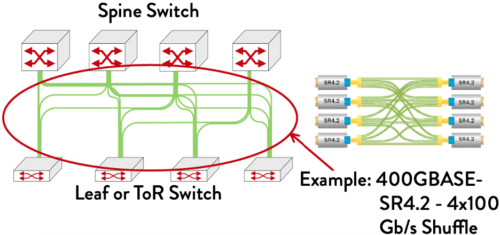
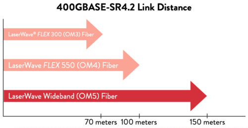
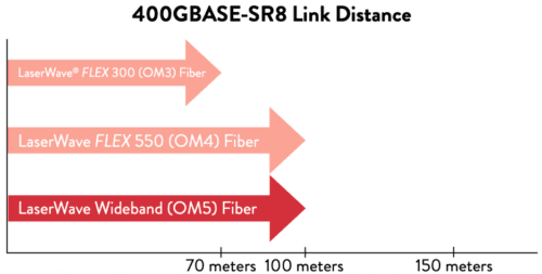
400GBASE-SR4.2 is the first multimode standard to use two wavelengths (850nm and 910nm), enabling 100 Gb/s transmission over a single fiber pair. It takes advantage of the multi-wavelength capabilities of OFS LaserWave® WideBand (OM5) fiber with 150 meter link distances, while supporting 100 meter links over LaserWave FLEX 550 (OM4) fiber and 70 meter links over LaserWave FLEX 300 (OM3) fiber. This builds on well-established 40 and 100G BiDi and SWDM technology that has been offered by switch and transceiver suppliers over the past decade. A key motivation for the 400GBASE-SR4.2 transceiver type is support of the installed base of multimode fiber cabling, designed around 100 meter reach over OM4 MMF, as well as extended reach over OM5 MMF, especially in large enterprise datacenters. 400GBASE-SR8 uses eight pairs of multimode fiber, with each pair supporting 50 Gb/s transmission. It operates over a single wavelength (850nm). OM4 and OM5 will support 100 meter links, while OM3 can support up to 70 meters. A key motivation for 400GBASE-SR8 is support of new cabling architectures in hyperscale datacenters.
What applications will use these links?
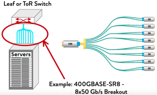
400 Gb/s multimode links can be used in a variety of applications. These include not only 400 Gb/s switch-to-switch (point-to-point) links, but several new applications, including 400GBASE-SR8 – 8x50GBASE-SR breakouts, or 400 Gb/s shuffles (fig. 1). The breakout application minimizes the number of ports on the Top-of-Rack (ToR) switch, providing connectivity to higher numbers of servers from a single switch. In similar fashion, the shuffle application allows a single 400 Gb/s switch port to support 100 Gb/s links to 4 different switches. 400GBASE-SR8 supports both flexibility and higher density: a 400G-SR8 OSFP/ QSFP DD transceiver can be used as 400GBASESR8, 2x200GBASE-SR4, 4x100GBASE-SR2, or 8x50GBASE-SR. 400GBASE-SR8 is already being deployed as 2x200GBASE-SR4. 5 THINGS YOU SHOULD KNOW ABOUT A Furukawa Company IEEE Std 802.3cm™-2020 For more information, visit our website at www.ofsoptics.com 1 2 Example: 400GBASE-SR8 – 8×50 Gb/s Breakout.
Shuffle Arrangement
Breakout Arrangement
What
does this mean for hyperscale data centers?
Both 400GBASE-SR4.2 and 400GBASE-SR8 applications can be used for point to point 400 Gb/s links between switches. Additionally, new applications are being deployed in hyperscale data centers. As server speeds reach 50 and 100 Gb/s, racks will contain fewer servers, leading to a change in switch architecture away from ToR to Middle-of-Row (MoR) or End-of-Row (EoR) switches. Copper DAC links are reaching link distance and bandwidth limitations that will make it very difficult to support this change in architecture, leading to demand for a low cost, short reach optical solution. 400GBASE-SR8 provides support for eight 50 Gb/s server links from a single MoR or EoR switch port, significantly increasing bandwidth density on the switch faceplate.
What does IEEE Std 802.3cm mean for enterprise data centers?
400GBASE-SR4.2 is the first 400 Gb/s
standard that takes advantage of the 4-pair OM3/OM4/OM5 infrastructure many
enterprises installed earlier, first for 40 Gb/s Ethernet and later, 100 Gb/s
100GBASESR4, and 200 Gb/s 200G-SR4. It provides a graceful evolution path for
enterprise networks, using the same cable infrastructure through at least four
Ethernet generations. Future advances point toward the ability to support even
higher data rates as they become needed. It takes advantage of the latest
multimode fiber technology, OM5 fiber, using multiple wavelengths to transmit
100 Gb/s over a pair of fibers over 150 meters, compared to 100 meters for OM4
and 70 meters over OM3.
400GBASE-SR8 will be used in enterprise data centers as 50 Gb/s servers are deployed. Most enterprise datacenter servers operate at lower data rates, however with 10 Gb/s server links being quite common.
What is coming next?
IEEE has already created a study group to investigate the development of 100 Gb/s per wavelength multimode solutions, known as the “100 Gb/s Wavelength Short Reach PHYs Study Group.” This will enable support of next generation 100 Gb/s server ports, expected in 2021-2022. By providing native 100 Gb/s support, no expensive “gearboxes” will be required to combine 50 Gb/s lanes, providing a low cost, power efficient optical solution. Beyond 2021-2022 timeframe, once an 800 Gb/s Ethernet MAC is standardized, using this technology with two-wavelength operation could create an 800 Gb/s, four-pair link, while a single wavelength could support an 800 Gb/s eight-pair link.
In today’s increasingly fast-paced, interconnected world, the need for high-speed broadband internet access and reliable wireless service is more acute than ever. The growth of fiber optic networks has allowed service providers to optimize FTTx — fiber-to-the-X, in which X can refer to various subscriber locations, including homes (H, as in FTTH) and buildings (B, as in FTTB) — with the most effective, cost-efficient connectivity and bandwidth capabilities.
Optical fiber solutions guarantee subscribers high-quality transmission of video, voice, and data while providing comprehensive end-to-end solutions for maximum return on investment (ROI). Fiber optics also allow subscribers to make use of recreational technologies such as HDTV, video on demand, and online gaming.
To reach and connect subscribers InvisiLight® Solutions, feature solid glass optical fiber bendable down to a 2.5-mm radius with practically zero loss. This innovative and patented technology provides a 500-fold improvement in bending loss over traditional approaches that use Single-Mode Fiber (SMF) type cables. The flexibility of this solution simplifies and hides installations by conforming to building corners, with no concern for bending loss or service disruptions.
WhatInvisiLight Indoor Living Unit (ILU) Solution Do I Need?
The OFS InvisiLight ILU Solution guide can help you decide which of the four InvisiLight ILU Solutions to use, based on your needs. Whether you are looking for low visibility, low cost, greater security, or ethernet connection for business we have the answer for you.
InvisiLight Indoor Living Unit (ILU) Solution Guide
History
Launched in 2012, the original, award-winning InvisiLight ILU Solution offered installers an innovative and simple method for indoor optical fiber installation. Since then we have launched added variations that are adaptable depending on customer needs. The process involves adhering a 0.9 mm diameter optical fiber into either crevices along ceilings and walls or moldings and walls. The result is a protected optical fiber link that is virtually invisible.
Very EZ
All InvisiLight products feature innovative OFS EZ-Bend® Optical Fiber. This fiber’s 2.5 mm minimum bend radius easily handles the sharp corners often met when installers conform optical fiber to a building.
When you are ready to order, or require more information, our experts are standing by ready to help. Simply fill out the form here.
This article in our technical series will focus on single-mode optical fiber geometries.
If you subscribed to our Light Post Emails, you know we previously covered bandwidth demand drivers and introductory standards as well as fiber optic dispersion. In this article, we’ll work our way through a typical fiber specification, highlighting the importance of various single-mode optical fiber geometry specifications.
Cladding diameter is the outer diameter of the glass portion of the optical fiber. For telecommunications fibers, this diameter has been 125 microns (µm) for a very long time. On the other hand, the diameter tolerance has not always been 0.7 µm.
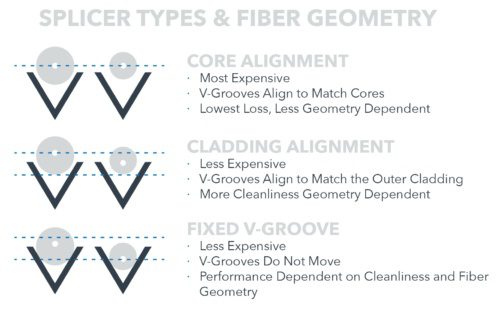
During the 1980s, optical fibers had outer diameter tolerances as high as +/- 3.0 µm. As you can imagine, matching up fiber cores ranging from 122 to 128 µm in diameter could result in extremely high loss. This situation is why fusion splicing machines required additional technology to help align the fiber cores. This extra technology increased the price of the splicing units.
Mode field diameter (MFD) is another specification related to fiber geometry. In a typical G.652.D compliant single-mode optical fiber, not all of the light travels in the core; in fact, a small amount of light travels in the fiber cladding. The term MFD is a measure of the diameter of the optical power density distribution, which is the diameter in which 95% of the power resides.
Clad non-circularity measures a fiber’s deviation from perfectly round, and is measured as a percentage difference versus perfect.
Core/Clad
Concentricity Error (Offset) of d 0.5 ¼m, < 0.2 ¼m typically
Core/clad concentricity error (CCCE) measures how well the core is centered in the fiber. CCCE is measured in microns and, of course, the closer the core is placed to perfect center, the better it is.
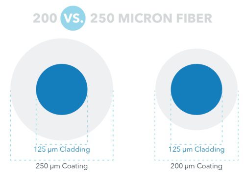
Although the difference between 200 and 250 µm is not
tremendously large, smaller diameter fibers can enable twice the fiber count in
the same size buffer tube, while also still preserving long-term reliability.
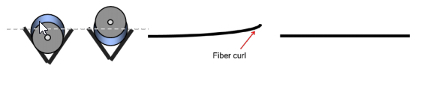
Fiber curl assesses the non-linearity of bare glass. In other
words, fiber curl measures how straight the glass fiber is when no external
stressors are present. If imbalanced stresses are frozen into a fiber during
the draw process, curl can result. This curl can show up during the splicing of
fiber optic ribbons or when fixed V-groove splicing machines are used.
In closing, fiber geekdom is a journey, not a destination, and there’s always more to learn. OFS has multiple decades of experience with fiber-optic cable networks. Please contact your local OFS representative if you would like additional information regarding optical fiber geometry specifications.
Distributed Acoustic Sensing (DAS) is a technology that enables continuous, real-time measurements along the entire length of a fiber optic cable. Unlike traditional sensors that rely on discrete sensors measuring at pre-determined points, distributed sensing utilizes the optical fibre. The optical fiber is the sensing element. These systems allow acoustic signals to be detected over large distances and in harsh environments.
AcoustiSens® Wideband Single-Mode Optical Fiber, the newest addition to the OFS LineaSens® family, is a vibration sensing fiber with optimal performance for DAS systems. Using a waveguide design based on the ITU-T G.657.A1 telecom-grade single-mode standard, AcoustiSens Wideband Optical Fibers significantly increase Rayleigh backscatter while maintaining low attenuation to improve Optical Signal to Noise Ratio (OSNR). Furthermore, the AcoustiSens Wideband Optical Fibers provide bend-insensitivity and expand the operating wavelength band (1536 – 1556 nm) ensuring interoperability with all known DAS interrogators.
AcoustiSens Wideband is intended for use in cables designed as sensing components in Distributed Acoustic Sensing (DAS) systems. Without the need for changes in interrogation equipment or complex optical amplification schemes AcoustiSens Wideband is a drop-in fiber replacement that provides greatly improved sensing performance with OSNR orders of magnitude better than telecom-standard fibers. This translates into significantly improved ASNR in DAS systems. Due to its waveguide design, AcoustiSens fibers are also bend-insensitive and splice compatible with G.657.A1 and G.652.D optical fibers, assuring smooth integration with commonly deployed sensing solutions.
AcoustiSens Optical Fibers are intended for use as components in optical and hybrid cables designed for vibration or acoustic sensing applications including:
Pipeline monitoring (midstream)
Rail monitoring
Perimeter monitoring
Subsea monitoring
Highway monitoring
Smart City applications
To learn more about AcoustiSens watch this video overview. Or you may contact us to discuss solutions to your sensing needs.
AccuCore HCF™ Optical Fiber Cable is the world’s first terrestrial hollow-core fiber (HCF) cable solution. Light travels about 50% faster in a hollow core optical fiber compared to the solid silica core of conventional fiber. Consequently, light transmitted in a hollow-core fiber arrives 1.54 microseconds faster for each kilometer traveled compared with conventional optical fiber.
The AccuCore HCF Optical Fiber Cable solution includes indoor/outdoor cable and termination with standard connectors, which are fusion-spliced to the patented photonic bandgap hollow-core fiber. OFS also offers installation services and both passive and active component selection to meet customer requirements. AccuCore HCF optical fiber cable has been successfully deployed, carrying live traffic in several networks.
This latest development from OFS was presented as a postdeadline paper on March 12, 2020 at the Optical Fiber Communication Conference and Exhibition (OFC) held in San Diego. OFC postdeadline papers represent the latest and most advanced technical achievements in the field. The paper reported error-free transmission of direct-detection 10 Gb/s DWDM signals over 3.1 km of cascaded cabled HCF. This is the first time that transmission results in a cabled HCF have been reported. That white paper is available here.
Contact OFS to learn more about AccuCore HCF fiber optic products.
The co-inventor of optical fiber, Dr. Peter Schultz, is a resident of the Virgin Islands. He was instrumental in convincing the local authorities back in the early 2000’s that the islands needed high-speed connectivity afforded by optical fiber. He assisted in the successful lobbying of federal and local governments to provide funding for the project and in 2009 The Virgin Islands Next Generation Network (ViNGN) was formed. This video shows how he partnered with OFS to deliver high-speed fiber connectivity to the U.S. Virgin Islands and specifically to his condo unit. OFS designed the fiber to the MDU (Multiple Dwelling Unit) network with the InvisiLight® Facade Solution using the 12-Fiber M-Pack® Indoor Outdoor MDU Drop Cable and SlimBox® Indoor Outdoor Enclosures. For inside the MDU, a SlimBox 64-Fiber Indoor Enclosure and the InvisiLight Indoor Living Unit (ILU) Solution were installed. OFS oversaw the installation for ViNGN with technicians from local contractor ADM Technologies, Inc.
This article focuses on the parameters that affect available bandwidth in optical fibers, and the dispersion mechanisms of various fiber types and non-linear effects. Dispersion describes the process of how an input signal broadens out as it travels down the fiber. There are several types of dispersions that we will cover. We’ll also take a cursory look at other important nonlinear effects that can reduce the amount of bandwidth that is ultimately available over an optical fiber.
Dispersion
Most of the traffic traveling through fiber networks takes the form of a laser pulse, where the laser is pulsed on and off, effectively forming a digital square wave comprised of “1”s and “0”s. Dispersion causes a pulse to spread out over time, effectively rounding the edges, and making it harder for the detector to determine whether a “1” or a “0” is being transmitted. When this happens, the effective bandwidth of the link is reduced. The three main types of dispersion mechanisms are modal dispersion, chromatic dispersion, and polarization mode dispersion. Because these mechanisms affect fiber networks in different ways, we’ll discuss each in some depth. Please download the full article for more information.
Modal Dispersion
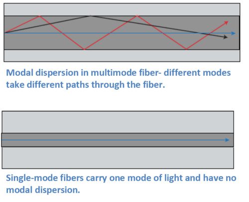
In general, our article on Single-Mode Optical Fiber Selection focuses on single-mode fibers since they comprise the vast majority of fiber kilometers deployed around the world. In contrast to multimode fibers, single-mode fibers are used for all high-capacity, long-distance networks due to their low attenuation and high bandwidth. A main limiting factor of multimode fibers is modal dispersion.
Multimode fibers carry multiple modes of light at the same time. While a mode of light can be thought of as a ray of light, a typical multimode fiber can have up to 17 modes of light traveling along it at once. These modes all traverse slightly different paths through the fiber, with some path lengths longer than others. Modes that take a straighter path will arrive sooner, and modes that bounce along the outer edges of the core of the fiber take a longer path and arrive later. The effect on the end pulse is called modal dispersion, since it is due to the different modes in the fiber. Multimode fibers are designed to reduce the amount of modal dispersion with precise control of the index of refraction profile, through the quantity of dopants used in the core. However, it isn’t possible to completely eliminate modal dispersion in multimode fibers.
Chromatic Dispersion
Chromatic dispersion describes a combination
of two separate types of dispersion, namely material dispersion and waveguide
dispersion. Light travels at different speeds at different wavelengths, and all
laser pulses are transmitted over a wavelength range. Light also travels at
different speeds through different materials. These varying speeds cause pulses
to either spread out or compress as they travel down the fiber. Fiber designers
can use these two points to customize the index of refraction profile to
produce fibers for different applications. Chromatic dispersion isn’t always a
bad thing. In fact, it can be used as a tool to help optimize network
performance.
For example, the first lasers used for fiber
transmission operated at 1310 nm, and many networks still use that wavelength.
Fiber designers therefore developed the first single-mode fibers to have
minimum or zero dispersion at this wavelength. In fact, G.652 fibers are still
designed this way. In these fibers, dispersion is higher in the 1550 nm window.
Today’s networks often operate with multiple
wavelengths running over them. In these networks, nonlinear effects that result
from the multiple wavelengths can affect network operation. We’ll give a brief
overview of some of these non-linear effects in this article. Chromatic
dispersion is often used as a tool to help optimize these types of networks.
Polarization Mode Dispersion (PMD)
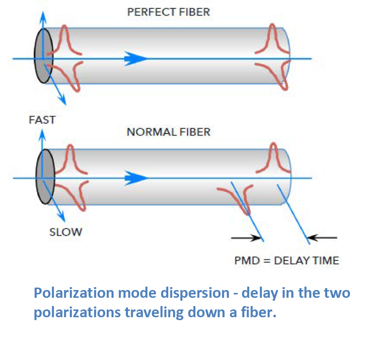
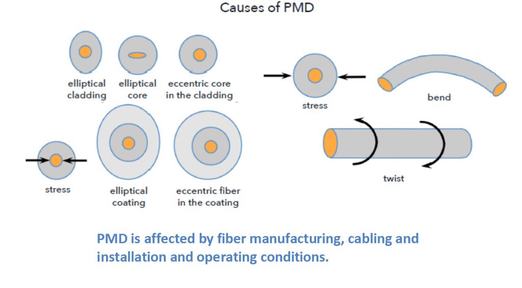
Light is an electromagnetic wave and is comprised of two polarizations that travel down the fiber at the same time. In a perfectly round fiber deployed with perfectly balanced external stresses, these polarizations would reach the end of the fiber at the same time. Of course, our world isn’t perfect. Even small amounts of glass ovality/non-concentricity or non-concentric stresses in the cable can cause one of the polarizations to travel faster than the other, spreading out in time as they travel along the fiber. This phenomenon is called polarization mode dispersion (PMD).
Cabling and installation affect PMD, and even
things like vibration from trains moving down tracks or wind-induced aerial
cable vibrations can affect PMD. However, the impacts of these interactions are
typically smaller than the inherent PMD caused by the glass manufacturing
process.
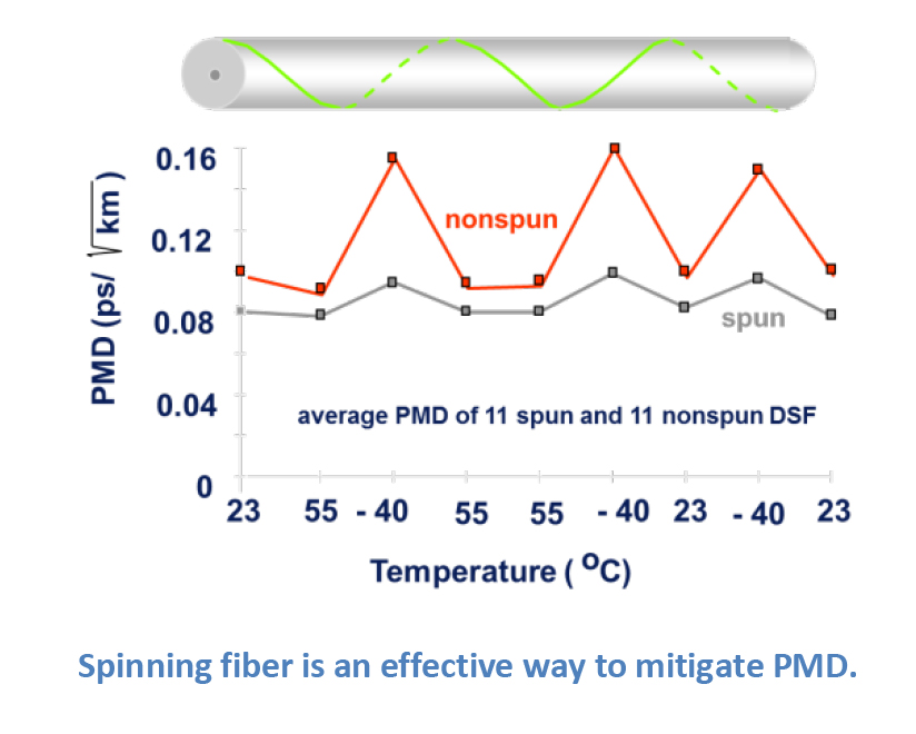
There are ways to mitigate PMD. One very
effective method is to make the glass fiber as geometrically round and
consistent as possible. OFS uses a special technique to accomplish this. Using
a patented process called fiber “spinning”; half-twists are translated through
the fiber during the draw process, reducing the non-concentricities and
ovalities in the glass that are the major contributors to increased PMD.
There are a host of other factors that
network, equipment, and fiber designers have needed to consider as network
capabilities have grown over the years. These factors often result as we
collectively add more and more wavelengths of traffic at greater speeds and
higher power levels.
It is not the intent of this article to review
each of these in depth, but instead to touch on them so the reader can have a
passing familiarity. The highest profile of these factors is four-wave mixing,
which led to the development of non-zero dispersion-shifted fibers (NZDF).
However, other non-linear effects include self-phase modulation, cross-phase
modulation, Raman and Brillouin scattering, and others. As mentioned earlier,
chromatic dispersion can be used to offset the effects of four-wave mixing. For
those non-linear effects related to higher power levels, increasing the
effective area where the light travels down the fiber can help to reduce the
impact of these other non-linear effects.
Dispersions and non-linear effects are the
least understood issues in the general fiber user population, mainly because
the guidelines used to match up today’s fibers and electronics typically work
so that the end user doesn’t need to have a detailed background to bring up a
system.
OFS has multiple decades of experience with fiber optic networks. Please contact your local OFS representative if you would like additional information regarding any of the items in this article.
OFS is a market leader in the design and manufacture of standard and custom Dispersion Slope Compensating Modules (DSCMs) also known as Dispersion Compensating Modules (DCMs). Our fixed broadband, reconfigurable, and tunable colorless modules round out a product line that is well-suited for the major transmission fiber types.
The fiber optic cable world has come a long way over the past 30 years. Products have become more rugged and user friendly, making it easier for people to enter the industry and work handling optical fiber and cable. While this is great for the industry, many people may understand the “how to” but not necessarily the “why” of fiber optics. To understand the “why” behind fiber and cable products, the next step is to become a full-fledged “fiber geek.” Because the industry changes so quickly, it’s important to understand fiber specifications are continuously changing.
Bandwidth demand continues
The demand for bandwidth continues unabated, driven by Web 1.0/2.0, mobile and now streaming video. The result is an expected Compound Annual Growth Rate (CAGR) of approximately 22% across the network through 2020.
While that’s somewhat old news, new bandwidth demand is on the horizon, potentially driven by several relative sources including 4K TV, virtual reality and an expansion of the “Internet of Things.”
Ultra HD TV, also known as 4K TV, first appeared on the radar screen approximately four to five years ago. While 4K TV offers twice the resolution of standard HDTV, the first models were priced at more than $20,000. Since then, the cost of 4K TV units has dropped rapidly to the point that they are now ubiquitously available at most electronics stores.
While linear TV packages still don’t offer many 4K programming options, over-the-top video providers such as Netflix and Amazon Video are rapidly adding content.
The primary reason that 4K TV is significant to bandwidth demand is that each 4K channel requires up to 25 Mbps, more than 2X the typical HD video requirement. Considering the number of TV screens that are typically on in a household, the potential demand could be a significant increase versus current HDTV demand levels.
High resolution screens are also an integral part of the experience promised by virtual reality. Virtual reality, while in its commercialized early stages, holds the promise of significantly changing the way that we experience media of all types. However, there’s a catch – fully- networked 4K virtual reality will require hundreds of megabits per second (or more) of bandwidth(1).
High resolution video will continue to use bandwidth as it becomes embedded in various networked applications such as telemedicine, remote medical monitoring and distance learning.
Why does optical fiber care?
This bandwidth demand can be satisfied in three ways: faster electronics, more wavelengths on the fiber and more optical fiber.
Standards are important
Fiber optic standards help to ensure a minimal level of network compatibility and performance. The standards-making process is an arduous one. Fiber standards are global, and standards makers strive to achieve balance and fairness. However, standards often provide only minimum performance levels. In fact, fibers that meet the standards may struggle with some current as well as future applications.
For this reason, it’s best to insist on fiber optic performance beyond the standards for many applications.
The demand for bandwidth is expected to continue far into the future, driven in part by requirements for breakthrough applications such as higher resolution video, virtual reality and other applications. We expect this demand to continue to drive the need for optical spectrum provided by fiber. Fiber standards, such as G.652 and G.657, are very important for network designers in setting minimum performance levels but can ultimately be insufficient to meet the requirements for future networks. For this reason, performance beyond the standards can be very important.
Optical fiber-to-the-business deployment is accelerating globally to support increasing internet speeds of up to 1 Gigabit per second, and 10 Gigabit speeds that are already available in some regions. Service providers are responding by installing optical fiber both to and deep inside buildings to the living unit.
The Solutions in this 64-page guide can help reduce both first and life cycle costs of optical fiber deployments to residential and business customers.
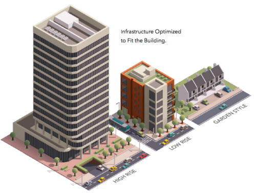
Solutions for both Greenfield installation during building construction and Brownfield installation in existing buildings are included. Scalable and optimized to fit a broad range of building structures, these solutions offer faster, reliable installation through innovative labor saving technologies, using less space than conventional approaches.
Solutions for both indoor and outdoor deployment offer flexibility to use the best available pathways for each building. The solution building blocks include a wide range of terminals, splitters, point-of-entry modules, riser cables, attic and wall fish fiber, hallway fiber and complete indoor living unit fiber kits. This portfolio allows service providers to select the best solution for each building, and OFS can help design building specific solutions and bills of material as a value added service.
OFS fiber-to-the-subscriber (FTTx) solutions help to revolutionize the speed of installing fibers; enhance the customer experience; minimize disruption; reduce labor costs; increase subscriber take rates; enable faster time to revenue for service providers; and get Gigabit and higher speeds faster to subscribers.
OPTICAL FIBER BUILDING CHALLENGES AND SOLUTIONS
Time to revenue: Fast and easy to install pre-terminated solutions can speed installation and reduce labor costs.
No pathways, requiring labor intensive cut and patch: Compact surface mounted fiber solutions.
Limited closet space: Smaller enclosures can enable installation of multiple operator connections in a small telecommunications closet.
Multiple boxes for splicing and splitter connections: Single box pre-terminated solutions can require less space and enable faster provisioning.
No duct space: Compact surface mounted fiber solutions either inside or on the outside of the building do not require duct.
Shared infrastructure: Compact cables can support multiple service providers in telecommunication pathways.
Fiber bends around many corners: Bend-insensitive fiber specified to support bend radius as low as 2.5 mm.
Disruptive/noisy to tenants: Optical solutions that are virtually invisible can be installed quickly and quietly and preserve the building decor.
Service disruptions and lost subscribers: Full solution of fiber, cable and connectors from one company, designed to work together. Factory tested to Tier 1 standards.
Multiple building types: Solutions to fit each building type.
PRE-TERMINATED vs. FIELD TERMINATED OPTICAL FIBER
Pre-terminated solutions are increasingly used to install fiber in Multiple Dwelling Unit (MDU) buildings to save time and money in higher labor cost regions. Pre-terminated products with built-in slack management are preferred so installers can neatly manage excess slack and use a single component to support multiple deployment lengths. Nevertheless, field terminated solutions can complement pre-terminated parts of the indoor or outdoor network and, for low labor cost markets, field terminated solutions may be preferred. OFS offers both pre-terminated and field terminated solutions to fit the needs of each service provider.
OPTICAL FIBER SPECIFICATIONS OPTIMIZED TO THE APPLICATION
Installing optical fiber in buildings and homes often requires conforming the fiber around sharp corners. EZ- Bend® Single-Mode Fiber offers outstanding bend performance down to a 2.5 mm radius for the most challenging in-residence and MDU applications. Compatible with the installed base of conventional G.652.D single-mode fibers, the fiber meets and exceeds ITU-T G.657.B3 recommendations. EZ-Bend fiber uses patented, groundbreaking EZ-Bend Optical Technology from OFS to provide three times lower loss at tight bends than competing G.657.B3 products.
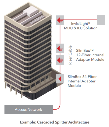
Centralized, Distributed and Distributed Cascaded Splitting
As FTTx deployment accelerates globally to meet increasing bandwidth needs, service providers must install optical fiber both to and inside the building for business and residential subscribers. Building types include duplexes, garden style, low rise (less than 10 floors), mid rise (10 to 15 floors), high rise (16 to 40 floors) and skyscrapers (40 floors and above). To provide building Gigabit services, providers must place optical cables in building risers and ducts, install optical fiber in hallways, and then take this fiber deep into the units, connecting to an indoor Optical Network Terminal (ONT). How can providers accomplish this in buildings that can vary widely in design, materials and available pathways?
Splitter Architectures
A typical PON network consists of the Optical Line Terminal (OLT) in a central office, head end or cabinet, connected by a feeder cable to optical splitters, and then to distribution cables downstream in the network. Choosing the right architecture depends upon end-user density, projected subscription rates and distance from the OLT. Splitter placement is important in FTTx design as it can significantly affect plant and electronics costs.
Three common types of splitter architectures are used when deploying FTTx:
Centralized splitting
Distributed splitting
Distributed cascaded splitting
To help meet these needs, the OFS portfolio supports all three splitter architectures, and features a broad range of solutions to meet the requirements of virtually any MDU deployment. For flexibility and regional preferences, these offers include a mix of pre-connectorized, in-field fusion splicing and mechanical connector solutions from which OFS can configure customized designs for each type of building.
Brownfield Outdoor Facade Solution
The Outdoor Facade Solution is used when property owners want to preserve the decor of the building exterior. The compact EZ-Bend Indoor/Outdoor cable is placed vertically on the exterior wall of the residence from an outdoor wall mount box to an indoor SlimBox® unit. The indoor SlimBox can be factory configured with SCA adapters or fanouts for a pre-terminated solution, or for fusion splicing. EZ-Bend jumpers are used for the path to each living unit. Pre-terminated EZ-Bend Jumpers are recommended for faster installation, or a mechanical connector may be used for field termination in the SlimBox Wall Plate. The 80×80 InvisiLight® Module can be used as a “fiber extension” to any location in the living unit. Alternatively, instead of EZ-Bend jumpers, the InvisiLight MDU solution may be placed in the hallway to the living units (not shown).
Brownfield Outdoor Facade Solution
Greenfield Pre-Terminated Solution
TELECOMMUNICATION ROOM
Compact basement box for a progressive customer activation;
The basement box (SlimBox 64F Terminal) allows fusion splices for the outside plant cable;
Ideal for buildings with low penetration rates: One splitter can be installed and the management of the customers is done through the SCA ports. A parking area permits easy connection of new customers;
Several boxes can be connected for modular expansion. Connections between multiple SlimBoxes are possible through access openings between them.
RISER BACKBONE
SCA pre-terminated cables for quick plug and play installation;
EZ-Bend patch cords directly from the apartment unit may be used for small buildings.
HORIZONTAL DEPLOYMENT
Direct deployment from the telecommunication closet to the apartment unit;
Ideal for Greenfield installation;
The EZ-Bend jumper is connected to an adapter installed in the SlimBox Wall Plate (inside the living unit).
INSIDE THE LIVING UNIT
An SCA mechanical connector can be used to terminate the EZ-Bend Jumper inside the living unit;
The InvisiLight ILU Solution is a complementary product used to extend the fiber inside the apartment.
Greenfield Fusion Spliced or Field Terminated Solution
TELECOMMUNICATION ROOM
Compact basement box for a progressive customer activation (parking up to 48 connectors in the SlimBox 64F Terminal);
The basement box (SlimBox 64F Terminal) allows fusion splices for the outside plant cable and the internal cables (up to 96 fusion splices – 8 splice trays with 12 splices in each one);
Ideal for buildings with low penetration rate: One splitter can be installed with management of the customers done through the SCA ports. A parking area permits easy connection of new customers;
Several boxes can be connected for modular expansion. Connections between SlimBoxes are possible through access openings between them.
RISER BACKBONE
ACCUMAX® cables may be used for quick and easy installation:
SCA pre-terminated pigtails are used for fusion splicing inside the basement and floor boxes.
HORIZONTAL DEPLOYMENT
Direct deployment from the telecommunication closet to the apartment unit through EZ-Bend cable (ruggedized 3.0 or 4.8 mm);
The horizontal cable is fusion spliced or field terminated with a mechanical connector in the SlimBox 12F Terminal (floor distribution box) and in the SlimBox Wall Plate (inside the living unit).
INSIDE THE LIVING UNIT
An SCA mechanical connector can be used to terminate the EZ-Bend Jumper inside the living unit or a pre-terminated pigtail can be used;
The InvisiLight ILU Solution is a complementary product used to extend the fiber inside the apartment.
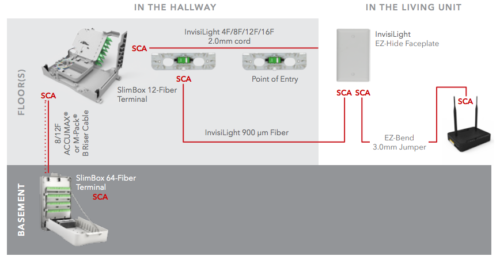
Compact basement box for progressive customer activation;
The basement box (SlimBox™ 64F Terminal) allows fusion splices to the outside plant cable;
Ideal for buildings with low penetration rate: One splitter can be installed with management of the customers done through the SCA ports. A parking area permits easy connection of new customers;
Boxes can be added for modular expansion. Connections between SlimBox units are easily made using jumpers through multiple ports designed into the box.
RISER BACKBONE
SCA pre-terminated cables for quick plug and play installation:
It is possible to place InvisiLight 2.0 mm 12-Fiber multifiber cord directly from the basement box and down hallways in small or garden style buildings.
HORIZONTAL DEPLOYMENT
The InvisiLight MDU Point of Entry (POE) Module offers a discrete solution using field termination inside the module;
Virtually invisible installation using the InvisiLight 12F Pre-terminated 2.0 mm cord.
INSIDE THE LIVING UNIT
InvisiLight ILU Solution is complementary and connects to the InvisiLight MDU installation;
InvisiLight ILU Solution is installed with the same tools and procedures as the InvisiLight MDU Solution
This 64-page guide with illustrations and part specifications will help in selecting the right fiber optic cables and accessories to reduce both the first and life cycle costs of fiber deployments to business customers inside buildings.
As transmission speeds over optical fiber networks in the enterprise increase to 10 Gigabits per second (Gb/s) and beyond, a relatively new term – “laser-optimized fiber” – has crept into the industry’s vocabulary. What is laser-optimized fiber? What do you need to know about it? And what exactly does the term “laser- optimized” mean? Understanding the answers to these questions will help you prepare for the latest wave in optical communications for enterprise networks.
Why have optical fibers been “optimized” for use with lasers?
Older “legacy” optical fiber systems (Token Ring, Ethernet, FDDI, ATM) used in premises applications operated at relatively slow speeds in the range of 4 to 155 Megabits per second (Mb/s). These systems utilized inexpensive light sources called Light Emitting Diodes (LEDs), which were perfectly adequate for these slower speeds. Multimode fibers used in these systems were rated to certain minimum bandwidths, typically:
160 MHz/km over 62.5/125 μm fiber at 850 nm
500 MHz/km over 50/125 μm fiber at 850 nm
500 MHz/km over both products at 1300 nm
These fibers were tested for bandwidth using an Overfilled Launch (OFL) test method, which accurately replicated real-life performance with an LED.
As the demand for bandwidth and higher throughput increased, especially in building and campus backbones, LEDs could not keep pace. With a maximum modulation rate of 622 Mb/s, LEDs would not support the 1 Gb/s and greater transmission rates required. One could make use of traditional lasers (Fabry-Perot, Distributed Feedback) typically used over single-mode fiber. However these are considerably more expensive due to the higher performance characteristics required for long-distance transmission on single-mode fiber.
In response, the industry developed a new high-speed laser light source called a Vertical Cavity Surface Emitting Laser (VCSEL). These VCSELs are inexpensive and well suited for low-cost 850 nm multimode transmission systems, allowing for data rates of 1 Gb/s and 10 Gb/s in the enterprise. With the emergence of these VCSELs, multimode fiber had to be “optimized” for operation with lasers.
VCSELs provide higher power, narrower spectral width, smaller spot size and faster data rates than LEDs. All of these advantages add up to a significant performance boost. This assumes, of course, the fiber itself does not hinder performance. To understand why this could occur, we need to recognize the differences between VCSELs and LEDs and how they transmit signals along a multimode fiber.
All LEDs produce a smooth, uniform output that consistently fills the entire fiber core and excites the many hundreds of modes in the fiber. The bandwidth of the fiber is determined by the aggregate performance of all the modes in the fiber. If a few modes lag behind or get ahead due to modal dispersion, they have little impact on bandwidth because many other modes are carrying the bulk of the signal.
The energy output of a VCSEL is smaller and more concentrated than that of an LED. As a result, VCSELs do not excite all the modes in a multimode fiber, but rather only a restricted set of modes. The bandwidth of the fiber is dictated by this restricted set of modes, and any modes that lag or get ahead have a much greater influence on bandwidth.
Typically, a VCSEL’s power would be concentrated in the center of the fiber, where older fibers were prone to defects or variations in the refractive index profile (the critical light-guiding property in the core of the fiber), resulting in poor transmission of the signal. That is why some fibers may actually perform poorly with a VCSEL compared to an LED.
To complicate matters, the power profile of a VCSEL is nonuniform and fluctuates constantly. It changes sharply across its face, varies from VCSEL to VCSEL and changes with temperature and vibrational fluctuations. Consequently, individual VCSELs will excite different modes in a certain fiber at any given time. And because different modes carry varying amounts of power, the fiber’s bandwidth can vary in an unpredictable manner.
Why are laser-optimized fibers the best choice for use with VCSELs?
With the advent of VCSELs, it became apparent that the traditional multimode fiber deployed for LED systems did not take full advantage of the performance benefits of VCSELs.
To fully capitalize on the benefits that VCSELs offered, fiber manufacturers developed laser-optimized multimode fiber (LOMMF). LOMMF is specifically designed, fabricated and tested for efficient and reliable use with VCSELs.
LOMMFs should have a well-designed and carefully controlled refractive index profile to ensure optimum light transmission with a VCSEL. Precise control of the refractive index profile minimizes modal dispersion, also known as Differential Mode Delay (DMD). This ensures that all modes, or light paths, in the fiber arrive at the receiver at about the same time, minimizing pulse spreading and, therefore, maximizing bandwidth. A good refractive index profile is best achieved through DMD testing.
VCSELs and LOMMF provide tremendous flexibility and cost efficiency in “freeing up” bandwidth bottlenecks in the enterprise today and well into the future. LOMMF is completely compatible with LEDs and other fiber optic applications (there are no special connectors or termination required and no effect on attenuation). LOMMF can be installed now and utilized at slower data rates until the need arises to increase network speed to 1 or even 10 Gb/s. At that point, you only need to upgrade the optics modules to VCSEL-based transceivers. There is no need to pull new cable.
Can you use any laser-optimized fiber for 10 Gb/s?
No — it is important to note that not all laser-optimized fiber is 10 Gb/s capable. If 10 Gb/s capacity is in your future, you must make sure that the LOMMF you’re installing now is capable of handling 10 Gb/s. The first laser-optimized fibers, introduced to the market in the mid-1990s, were designed for 1 Gb/s applications. Available in both 62.5/125 µm and 50/125 µm designs, these fibers extended the reach capability of 1 Gb/s systems beyond what the industry standards stated. For instance, OFS 1 Gb/s Laser Optimized 62.5 Fiber can go 300 meters in cost-effective, 1 Gb/s 850 nm (1000BASE-SX) systems. 50/125 µm fibers offer even greater performance, with a reach of 600 meters or more. These 1 Gb/s LOMMFs, coupled with 850 nm VCSELs, allow for the lowest systems cost for building backbones and short-to medium-length campus backbones
How do you measure bandwidth for laser-optimized fiber?
Since LEDs have a uniform and consistent power profile that excites all the modes in a multimode fiber, the traditional OFL method of bandwidth measurement accurately predicts bandwidth of fiber for LED applications. But because VCSELs only excite some of the modes in a fiber, and in a varying manner, the OFL bandwidth measurement cannot predict what the fiber’s bandwidth would be if the fiber were to be used in a VCSEL application.
It should become clear now why fiber manufacturers developed laser-optimized fiber, and why DMD testing is so important. The refractive index has to be well designed and controlled to ensure that all modes exhibit minimal DMD and all arrive at the other end of the fiber at the same time. No matter which modes in the fiber are actually guiding the light, those modes will have minimal DMD and provide high bandwidth.
What should you look for in DMD testing?
DMD testing provides a clear picture of how individual mode groups carry light down the fiber, and which mode groups are causing DMD. In fact, that picture is so clear that the standards require fiber to be DMD-tested to ensure adequate bandwidth to the rated distances for 10 Gb/s applications.
Tony Irujo is sales engineer for optical fiber at OFS, a world-leading designer, manufacturer and provider of optical fiber, fiber optic cable, connectivity, fiber-to-the-subscriber (FTTx)and specialty photonics products. Tony provides technical sales and marketing support for multimode and single-mode optical fiber.
Tony has 25 years of experience in optical fiber manufacturing, testing and applications. He started with SpecTran in 1993 as a quality and process engineer and transitioned to more customer-focused roles with Lucent and OFS. He represents OFS in the Fiber Optic LAN Section (FOLS) of the TIA, has authored several papers on fiber technology and applications and is a frequent speaker at industry events. Tony has a Bachelor of Science degree in Mechanical Engineering from Western New England College in Springfield, MA.

 In today’s increasingly fast-paced, interconnected world, the need for high-speed broadband internet access and reliable wireless service is more acute than ever. The growth of fiber optic networks has allowed service providers to optimize
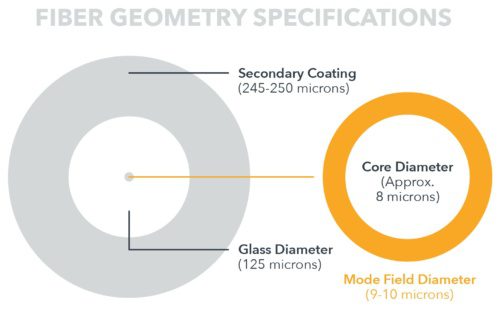
 Distributed Acoustic Sensing (DAS) is a technology that enables continuous, real-time measurements along the entire length of a fiber optic cable. Unlike traditional sensors that rely on discrete sensors measuring at pre-determined points, distributed sensing utilizes the optical fibre. The optical fiber is the sensing element. These systems allow acoustic signals to be detected over large distances and in harsh environments.
 The co-inventor of optical fiber, Dr. Peter Schultz, is a resident of the Virgin Islands. He was instrumental in convincing the local authorities back in the early 2000’s that the islands needed high-speed connectivity afforded by optical fiber. He assisted in the successful lobbying of federal and local governments to provide funding for the project and in 2009 The Virgin Islands Next Generation Network (
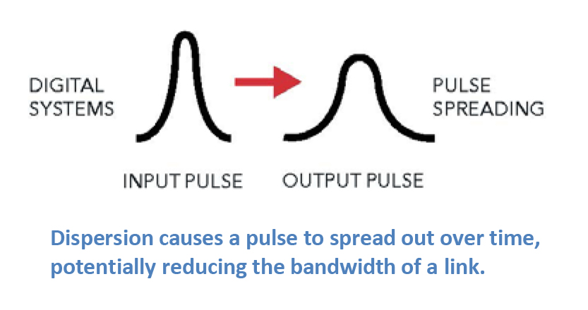
 The demand for bandwidth continues unabated, driven by Web 1.0/2.0, mobile and now streaming video. The result is an expected Compound Annual Growth Rate (CAGR) of approximately 22% across the network through 2020.
 High resolution video will continue to use bandwidth as it becomes embedded in various networked applications such as telemedicine, remote medical monitoring and distance learning.
 A typical PON network consists of the Optical Line Terminal (OLT) in a central office, head end or
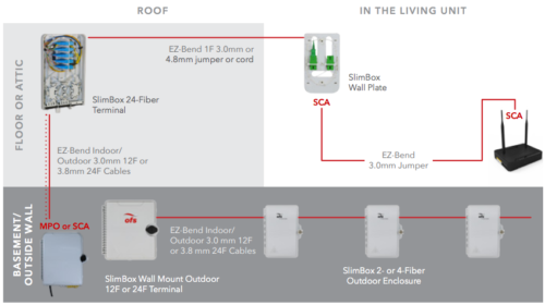
 No — it is important to note that not all laser-optimized fiber is 10 Gb/s capable. If 10 Gb/s capacity is in your future, you must make sure that the LOMMF you’re installing now is capable of handling 10 Gb/s. The first laser-optimized fibers, introduced to the market in the mid-1990s, were designed for 1 Gb/s applications. Available in both 62.5/125 µm and 50/125 µm designs, these fibers extended the reach capability of 1 Gb/s systems beyond what the industry standards stated. For instance, OFS 1 Gb/s