
Placing Fiber Optic Cable in Underground Plant
1. Overview
This document covers cable placing in conduit, innerduct, handholes, and manhole structures. The innerduct may be direct buried or placed in larger diameter conduits. In some applications, the innerduct may be lashed to an aerial strand.
This document covers conventional cable placing techniques that are used to pull or blow (cable jetting) the cable into the conduit or innerduct.
> Download full Article for more details
2. General Rules
2.1 Route Survey and Inspection
It is recommended that an outside plant engineer conduct a route survey and inspection prior to cable installation. Manholes and ducts should be inspected to determine the optimum splice locations and duct assignments. A detailed installation plan, including cable pulling or blowing locations, intermediate assist points, and cable feed locations should be developed based on the route survey.
2.2 Maximum Rated Cable Load
The maximum rated cable load (MRCL) for most OFS outside plant fiber optic cables is 600 lb; however, the cable documentation should always be checked because lower values of MRCL may apply for some cables. When using pulling equipment to install cable, measures should be taken to ensure that the MRCL is not exceeded. This includes the use of breakaway swivels, hydraulic pressure relief valves, and electronic tension control systems.
2.3 Minimum Bend Diameter
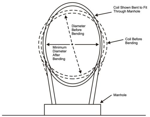
The minimum bend diameters for OFS cables are defined for both dynamic and static conditions. The dynamic condition applies during installation when a cable may be exposed to the MRCL, e.g., while pulling the cable around a sheave or capstan.
2.4 Temperature Limits
Storage and installation of OFS fiber optic cable is limited to the temperature ranges. Be aware that solar heating due to sunlight exposure can increase the cable temperature well above the ambient temperature.
3. Underground Optical Cable Precautions
Before starting any underground cable placing operations, all personnel must be thoroughly familiar with local company safety practices. Practices covering the following procedures should be given special emphasis:
> Download full Article for more details
4. Innerduct
Fiber optic cable is most often placed in a small-diameter innerduct rather than a large-diameter conduit. For existing conduit structures, multiple innerducts can be placed in a single conduit to provide multiple cable paths in the duct. Innerduct is also recommended because it provides a clean continuous path for the installation of the fiber optic cable.
4.1 Diameter Ratio and Area Ratio
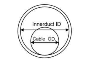
Diameter ratio and/or area ratio are used to determine the optimal cable OD that should be installed in an innerduct. Either ratio can be used, but consistently using one or the other is important to avoid confusion.
4.2 Direct Buried Applications
Studies have shown that vertical undulations in direct buried innerduct can greatly increase the required cable installation forces.
5. Cable Lubricant
Cable lubricant should be used when placing fiber optic cables. Recommended cable lubricants include Polywater4, Hydralube5, and similar cable lubricants that are compatible with polyethylene cable jackets. Both the winch line (or pulling rope) and the cable should be lubricated.
> Download full Article for more details
6. Cable Placing Methods
6.1 Backfeed Technique
The backfeed technique is a common installation method that is used to divide the cable installation into two separate pulls. The backfeed technique may also be used near equipment offices when one end of the cable must be pulled by hand into the building, or at manhole locations where the cable route changes direction.
6.2 Forward-Feed Technique
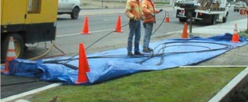
In the forward-feed technique, the leading end of the cable and excess cable length are pulled out of the innerduct at an intermediate manhole and stored on the ground in a figure-eight. This technique can be used multiple times during a cable installation to greatly increase the distance between cable splices.
6.3 Figure-Eight Installation Techniques
If figure-eight techniques are used during cable installation, the cable should be handled manually and stored on the ground. Place the cable on tarps to prevent damage from gravel, rocks, or other abrasive surfaces.
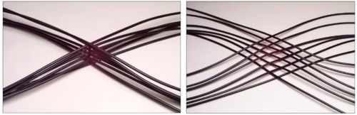
When figure-eighting heavy cables (264 fibers or more), the cable stack should be offset to prevent sheath dents and cable damage. Although sheath dents do not typically damage fibers, this type of cosmetic damage is undesirable. When utilizing the offset method, each crossover point of the cable stack should be offset about 2 inches instead of being stacked directly on top of each other.
6.4 Handholes
Handholes are frequently used to provide access to cable splices and slack storage coils. On long cable pulls, handholes may be used to facilitate intermediate-assist placing operations. The intermediate-assist handholes are typically installed near obstacles or at a predetermined spacing that coincides with the maximum expected cable installation length.
7. Pulling Fiber Optic Cable
The following instructions assume general familiarity with outside plant cable placing procedures. They also assume that the innerduct is in place and a lubricated pulling tape or rope has been installed in the innerduct.
7.1 Feed Manhole
Mount the cable reel on the reel carrier so that the cable feeds off the top of the reel. Position the cable reel adjacent to the manhole and in-line with the innerduct. The cable reel should be positioned close enough to the manhole so that excessive cable length is not dragging on the ground, but far enough away to maintain slack cable in the event of a sudden start or stop during the pulling operation. A distance of 10 – 15 feet is generally sufficient. Attach the pull line to the fiber optic cable using a cable grip and swivel connector. Caution: A breakaway swivel connector is required if a tension limited winch is not used to pull the cable.
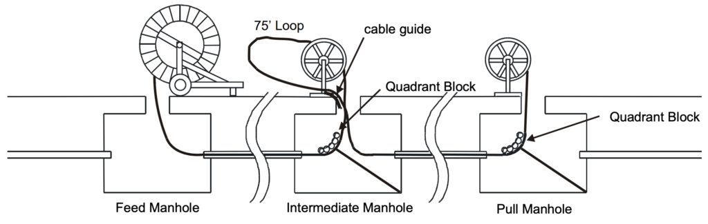
7.2 Intermediate Manholes
The innerduct in intermediate manholes may be continuous through the manhole or it may be interrupted. In either case, the innerduct should be positioned in a straight path from entry duct to exit duct. If the innerduct is continuous and has been racked, remove the innerduct ties and straighten the innerduct through the manhole. If necessary, slack innerduct can be cut out using an innerduct cutter. Secure the innerduct in the manhole to prevent it from creeping into the main duct during cable placing operations.
> Download full Article for more details
7.3 Pull Manhole
OFS recommends the use of tension-limited winches for pulling fiber optic cable. The tension control may be accomplished by electrical, mechanical, or hydraulic methods. In any case, the tension-limiting device must be routinely calibrated as recommended by the equipment manufacturer. Cable winches that display cable tension but do not have automatic cutoff are not sufficient to protect the cable. If a tension-limited winch is not used, a breakaway swivel must be used to connect the fiber optic cable to the pulling line.
7.4 Capstan Winches
7.4.1 General
Breakaway swivels do not protect the fiber-optic cable after the cable pulling-eye passes the intermediate capstan winch; therefore, intermediate-assist capstan winches must be tension-limited. The capstan must also meet the minimum cable bend-diameters.
7.4.2 Set-up
The capstan winches should be positioned along the cable route where the expected pulling tension will be 600 pounds or less. Proper positioning of the capstans prior to the start of the pull will eliminate construction delays caused when an unplanned intermediate capstan assist must be added to the placing operation.
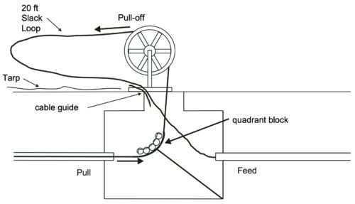
7.4.3 Slack Cable Loop
During the pulling operation, a slack loop of cable must be maintained on the pull-off side of the capstan as shown in Figure.
7.4.4 Adding Intermediate Capstans
If an intermediate capstan is added during the cable pull and the cable pulling eye has already passed through the manhole, a loop of slack cable must be pulled to the intermediate manhole before cable is wrapped on the capstan.
7.4.5 Removing Cable from Intermediate Capstan Assist Winch
At the conclusion of the pull, the cable on the capstan is twist free. However, one twist per wrap will be generated in the cable if it is removed from the capstan and straightened.
8. Blown Optical Cable Installation
Cable blowing systems use high-pressure, high-velocity airflow combined with a pushing force to install the cable. A hydraulic or pneumatic powered drive wheel or drive belt is used to push the cable into the innerduct at the feed manhole. Controls and gauges on the cable blowing system allow the operator to monitor and adjust the air flow and push force that is exerted on the cable. Some cable jetting systems use a plug at the cable end to capture the compressed air and generate a small pulling force on the end of the cable.
9. Optical Cable Coiling
9.1 Coils Stored at Intermediate Holes
Many end users require that coils of slack cable be stored in intermediate manholes along the cable route. These slack storage coils are used for future branch splices or route rearrangements. It is important that the coiling method accommodates the proper coil diameter and does not introduce kinking or excessive twist into the cable.
9.2 Fold-Over Method
The Fold-Over Method is recommended for storing moderate lengths of slack cable. Form a cable bight and then twist the bight to form the first cable coil. Fold the coil over to form the second cable coil.
> Download full Article for more details
9.3 Teardrop Method
The teardrop coiling method is recommended for storing longer lengths of cable since it is easier to roll the cable than perform repetitive folding operations. The cable is stored twist free by rolling the cable bight in a manner similar to that used on the cable end.
9.4 Garden Hose Method
The garden hose method is recommended for large diameter cables because only one turn of cable is handled at a time. The storage coil can be formed directly on the manhole racking as each additional loop is added. Each loop can be taped in place as it is added to the storage coil. This method can be used to store any length of slack cable.
9.5 Coils Stored at Splice Locations
Slack cable must be stored at splice locations to allow for splicing. Typically, a cable length of 50 to 100 feet is required for splicing purposes; however, the actual cable length may vary depending on the accessibility of the manhole.
10. Racking Fiber Optic Cable and Innerduct
Cable racking normally begins in intermediate manholes and proceeds manhole by manhole toward each end of the cable. Slack for racking the fiber optic cable may come from either the feed or the pull manhole depending on which end is closer and the amount of excess cable that is available. The preferred method of obtaining racking slack is pulling by hand. If the cable cannot be moved by hand, a split cable grip can be attached to the cable and the cable can be pulled using a cable winch or a chain hoist. Do not exceed the maximum tension rating or violate the minimum bending diameter of the cable while pulling the slack.
Cable coils should be racked in a location where they will not be damaged, preferably on the manhole wall behind in-place cables. Do not decrease the diameter of the cable coils. If slack cable must be removed from the coil for racking purposes, remove one or more loops from the coil and then enlarge the coil to absorb excess slack. Tie the coil securely in place with plastic ties.
> Download full Article for more details
Tags: fiber optic cables