This practice provides instructions for sheath removal and mid-span access of OFS AccuTube+ Rollable Ribbon optical fiber cables. It is intended for personnel with prior cable splicing experience. Working familiarity with cable access tools, splicing equipment, and splice closures is necessary as this guide does not cover all aspects of cable splicing.
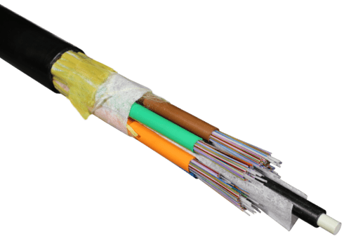
AccuTube+ cables contain OFS Rollable Ribbon fiber in a traditional loose tube cable design. AccuTube+ cables are available in fiber counts from 432 to 3456 fibers.
Contents
- Precautions
- Recommended Tools
- Ribbon Termination
- Sheath Removal for Single Jacket AccuTube+ Cables End Prep/Butt Splice Applications
- Sheath Removal for Single Jacket AccuTube+ Cables Mid Span/Express Applications
- Armor Tape Removal for Single Jacket AccuTube+ Cables End Prep/Mid Span Splice Applications
- Additional Resources
Precautions
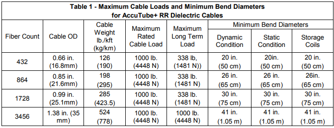
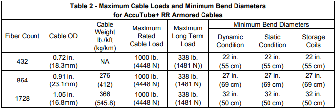
OFS optical fiber cables are designed to meet the rigors of aerial, direct buried and underground duct environments. However, care must be exercised during installation to ensure that the maximum rated cable load (MRCL) is not exceeded or that the minimum cable bend diameter is not violated.
Cable minimum bend diameters1 are typically expressed as a multiple of the cable outside diameter (OD) under static and dynamic conditions. The static condition represents an installed cable that may be subjected to long-term residual load. The dynamic condition represents a cable during installation which may be subjected to the full tensile load rating of the cable. For AccuTube+ cable, the minimum bend diameter under both static and dynamic conditions is 30 OD. See Tables 1 and 2 for further details.
Cable tensile load ratings are also specified for both static and dynamic conditions. The dynamic condition represents a cable during installation when it may be subjected to the maximum rated cable load (MRCL). The static condition represents an installed cable that may be subjected to a long-term residual load. The MRCL load for AccuTube+ optical fiber cable is 1000 pounds (4448 N) and the maximum long-term load is 333 pounds (1481 N).
Breakaway pulling swivels and/or calibrated pulling devices are recommended for use during cable installation to protect the cable from excessive installation forces. Cable lubricants are also recommended during cable installation. Contact OFS or a cable lubricant manufacturer for guidance on proper lubricants to be used with optical fiber cable.
Recommended Tools
- Cable sheath knife
- Scissors
- Cable shears
- Diagonal cutters
- Pliers
- Seam ripper
- Co-Axial cable tube cutter (ring cut of AccuTube+ 432- and 3456-fiber cables)
- Jonard MS-26 Large Mid Span Slitter tool (mid-span access of AccuTube+ 432 and 3456-fiber cables)
- OFS Quick Split RT tool (ring cut and mid-span access of AccuTube+ 864 and 1728-fiber cables)
- Electrical tape
- Tape measure
- Lint-free wipes and Isopropyl Alcohol
- Gloves and safety glasses
Caution: Safety glasses should always be worn when working with optical fiber cable
How to Splice Rollable Ribbon (RR) Fiber Optic Cable
Ribbon Termination
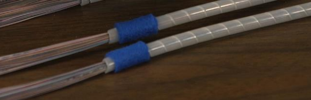
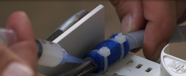
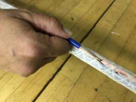
OFS recommends the use of clear spiral tubing for transporting and protecting the Rollable Ribbons in the splice closure (Figure 1). The Rollable Ribbons should be terminated by injecting a one-inch (2.5 cm) long section of RTV silicone sealant into the end of the spiral transportation tube (Figure 2). For small diameter tubes, a disposable syringe is recommended for injecting the RTV. OFS recommends Momentive RTV 108 silicone rubber adhesive sealant3 for this application. The RTV sealant becomes tacky after about 30 minutes and reaches full cure in about 10 hrs. The RTV plug is recommended to prevent fiber movement in cold temperature environments.
Recommended Materials for Ribbon Termination
- Momentive RTV 108 Silicone Rubber Adhesive
- McMaster-Carr, plastic syringe with taper tip, part# 7510A661, or equivalent.
- Nelco HT 3/8-C clear spiral tubing
Sheath Removal for Single Jacket AccuTube+ Cable – End Prep/Butt Splice Applications
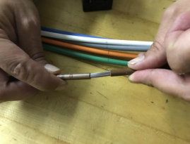
Single jacket AccuTube+ cable is manufactured using OFS 12 fiber Rollable Ribbons. AccuTube+ cables are available in fiber counts of 432, 864, 1728, and 3456 and contain 4.5 mm, 6.0 mm, 7.0, and 5.0 mm buffer tubes, respectively.
- Consult the closure manufacturer instructions for the correct length of cable to be prepped.
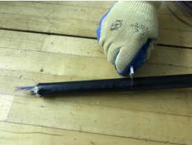
- Use a cable sheath knife to ring cut the cable jacket six inches from the end. Make a horizontal cut along the cable jacket to the end of the cable.
- Use the cable sheath knife to ring cut the cable at the length required for jacket removal. Lightly score the cable jacket rather than cut all the way through.
- Gently flex the cable with a circular motion at the score mark. Be careful not to violate the minimum bend radius. The cable jacket will separate at the score mark.
- Remove the cable jacket from the end of the cable.
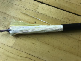
- Pull the rip cord from the cable opening to the second ring cut in the cable. Remove the cable jacket.
- Remove the aramid yarn from the end of the cable.
- Use a seam ripper or cable sheath knife and cut the binder threads along the cable opening.
- Remove the binder threads and water blocking tape to expose the buffer tubes.
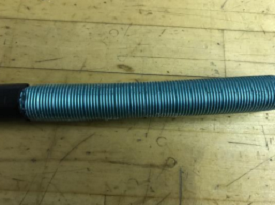
- Trim the central strength member as required for the closure assembly.
- Mark the buffer tubes and ring cut with the following tools. For the 432 and 3456 fiber cables use the Ideal Coaxial cutter #45-163.
Use the OFS Quick Split RT for the 864 fiber cable (6.0 mm opening) and the 1728 fiber cable (7.2 mm opening).
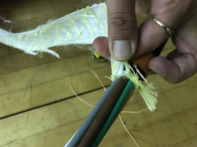
- Score and snap the tubes to expose the fibers and remove the tube by pulling towards the end.
Sheath Removal for Single Jacket AccuTube+ Cables – Mid Span/Express Applications
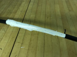
- Measure and ring cut the section of cable jacket that will be installed in the closure. Measure a 10 inch window in the center of the jacket opening and ring cut with a sheath knife. Make a longitude cut through the cable jacket and remove.
- Cut the rip cord in half and pull it through the outer jacket in both directions to the ring cuts on each side of the jacket opening.
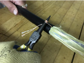
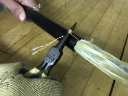
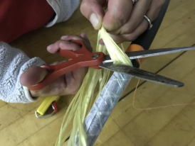
- Cut the aramid yarn at each end of the cable opening and remove.
- Use a seam ripper or cable sheath knife and cut the binder threads along the cable opening.
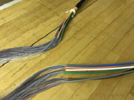
- Remove the binder threads and water blocking tape to expose the buffer tubes.

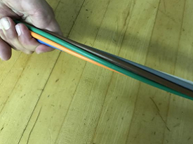
- Unwind the buffer tubes from the strength member.
- Trim the central strength member as required for securing to the closure.
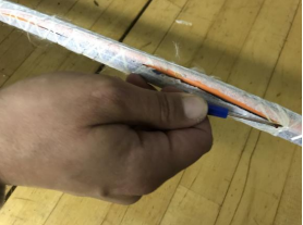
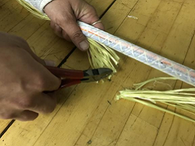
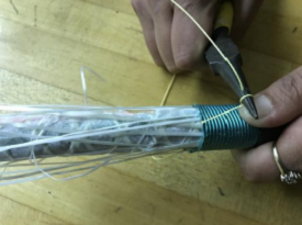
- Mark the buffer tubes as required for removal. Split and ring cut the tubes as follows.
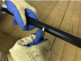
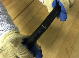
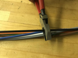
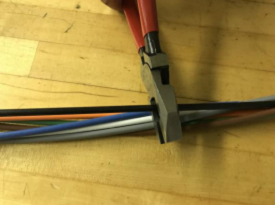
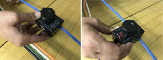
For the 432 and 3456-fiber cables, use the Jonard MS-26 Large Mid-Span Slitter tool to first slit the tube (Left Figure). Use the Ideal Coaxial cutter #45-163 to ring cut the tube after splitting (Right Figure).
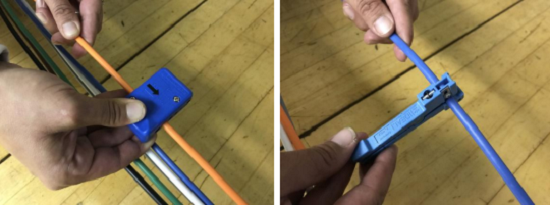
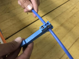
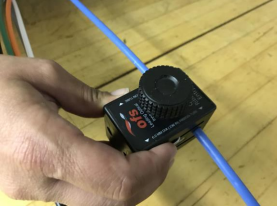
For the 864 and 1728-fiber cables, use the OFS Quick Split RT tool to first slit then ring cut the tubes.
- Remove the split tubes from the fiber. Install the spiral transportation tubing and complete the closure assembly as required.
Armor Tape Removal for Single Jacket AccuTube+ Cables – End Prep/Mid Span Splice Applications
- Remove six inches of the outer cable jacket for end prep, or ten inches of outer cable jacket for a mid-span entry.
- Score the armor tape at the required length for installing the bonding hardware. Two ripcords are provided to separate the armor tape into two pieces. Pull the ripcords through the armor tape to the score mark. Remove to expose the buffer tubes. Ground the armor tape as required by local policy or codes.
- Install the spiral transportation tubing and complete the closure assembly as required.
Additional Resources
- Download a PDF of these instructions.
- Learn more about out Rollable Ribbon Fiber Optic Cable on Youtube
- OFS IP-031A, Use & Care of OFS Quick Split RT Tool
- OFS IP-089, Fusion Splicing Recommendations for OFS Rollable Ribbon Using the Fitel S123 M12 Fusion Splicer
- AccuTube+ cable prep, rollable ribbon splicing, and & closure assembly videos can be found on our YouTube channel at: https://www.youtube.com/user/OFSoptics
For additional information please contact your sales representative. You can also visit our website at www.ofsoptics.com or call 1-888-FIBER-HELP (1-888-342-3743) from inside the USA or 1-770-798-5555 from outside the USA.
_________
1 Some cable manufacturers specify minimum bend radius rather than minimum bend diameter. Minimum bend diameters can be converted to minimum bend radius by dividing the minimum bend diameter by two. For example, the minimum bend radii for AccuTube+ cable is 15 cable OD for both static and dynamic conditions.
OFS reserves the right to make changes to these instructions at any time without notice. This document is for informational purposes only and is not intended to modify or supplement any OFS warranties or specifications relating to any of its products or services. OFS makes no warranty or representation with respect to the non-OFS products or non-OFS companies mentioned in this document.