
HOW TO SPEAK “FIBER GEEK” | ARTICLE 3: FIBER RELIABILITY
Leave a CommentWELCOME BACK, FIBER GEEKS!
Article 1 in this series focused on growth in bandwidth demand and attenuation in optical fibers caused by bending, and the built-in mechanisms scattering and absorption. Article 2 focused on several types of dispersion that exist in fiber.
This article, the third in the series, will focus on fiber strength and reliability.
FIBER RELIABILITY
Except for products specifically intended for short time use only, lifetime and durability are normally of rather high importance for the user. As for optical fibers, the installation of the cabled fibers is typically both time consuming and very costly, and so reliability and lifetime may be even more important.
Historically this has resulted in a lot of focus on fiber lifetime, and although materials for optical fiber manufacture have been under constant improvement over the last 30 – 40 years, the longevity of even some of the first fiber optic cables is impressive.
Unlike most other fiber properties, we are here dealing with statistical properties which are difficult and time consuming to measure, and the exact lifetime of an individual fiber cannot be predicted.
As such this is not different from lifetime considerations for other products, but failure consequences may typically be more severe.
Fiber has a reputation for excellent reliability, and that hasn’t been acquired by luck. For most end users, fiber just works, and they don’t give the topic much thought. However, this performance is based on a deep understanding of the mechanical performance of the glass to the molecular level. Researchers have spent entire careers acquiring this understanding and translating this knowledge to product design, manufacturing, and installation recommendations.
WHY DO FIBERS BREAK?
For starters, pristine glass optical fiber is stronger than steel, when measured diameter to diameter. Although the actual intrinsic strength of glass can vary according with sample preparation, it is often greater than 700,000 pounds/square inch (PSI), compared to 70,000- 85,000 PSI for cold rolled steel.
Although glass is very strong, it is brittle so it cannot be stretched for large amounts without breaking. Imperfections and mechanical flaws may weaken the glass significantly as may impurities even as small as fractions of a micron.
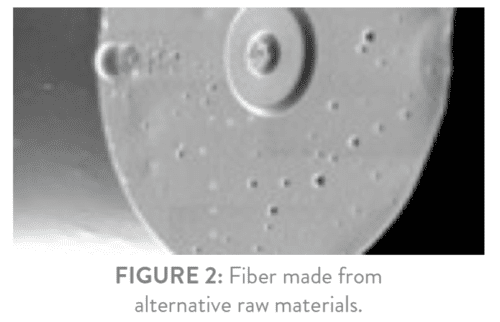
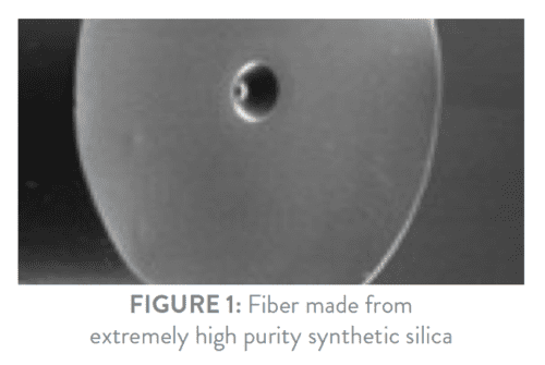
In order to limit the number of impurities to an absolute minimum, OFS use synthetic silica to make our glass. Synthetic silica (SiO2) is hence made from ultra-pure chemicals which are pure to the parts per billion level, and the actual core of the fiber is pure to the 10 parts per trillion level. It would resemble allowing only one bad rice-grain in a 20 ft standard shipping container filled with good rice. By keeping such an extremely high glass purity, the risk of fiber weakening because of impurities is minimized. Other manufacturing methods may not provide similar high purity of the finished glass fiber.
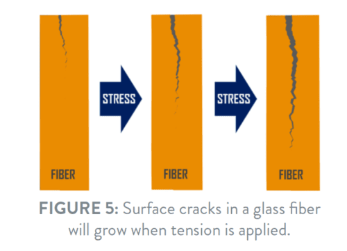
But impurities are not the only reasons that may cause a fiber to break. A glass surface typically contains a number of cracks of different sizes. This is true for fiber glass surfaces as well, and when stress is applied to the fiber, the cracks will grow larger. As might be expected, a large stress on the fiber will cause fiber cracks and other flaws to grow more rapidly than if only a small stress is applied to that fiber.
There may be a huge difference in the speed by which the cracks grow, and this may not always seem obvious. More on that later.

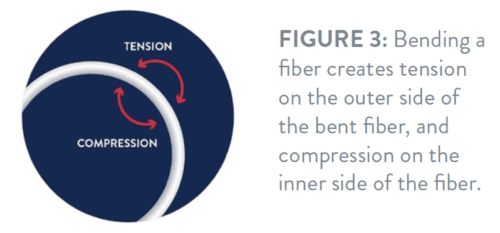
Another issue which may not seem obvious is that stress is also applied to a fiber simply by bending that fiber. As shown in Figure 3 the outermost surface of a fiber bend will be stretched and result in tension – whereas the innermost surface will be compressed. Compression does not cause cracks in the fiber surface to grow larger – but tension does.
It probably seems more obvious that tension applied along the length of the fiber (typically by pulling the fiber) will also cause cracks and flaws to grow.
When cracks or flaws grow larger the strength of the fiber is reduced because a smaller cross section of the fiber is now holding the fiber together. So, a fiber with large cracks or flaws will break at a lower strain than a pristine fiber containing only small (or no) cracks.
To ensure that no large cracks or flaws are present in the fiber, a manufacturing step called “proof testing” is added after the actual making of the fiber. During proof testing, every 1 – 2 meter section of the fiber is subjected to a relatively large strain. So large that it makes the fiber 1% longer. Under such large strain cracks and flaws in the fiber will grow quickly, and if the cracks are large enough the fiber will simply break. This ensures that after proof testing no large cracks or flaws exist in the fiber anymore. However, small cracks and flaws will still be present and that is why the glass production method is so important. The purer the glass, the less likely problems will occur long term.
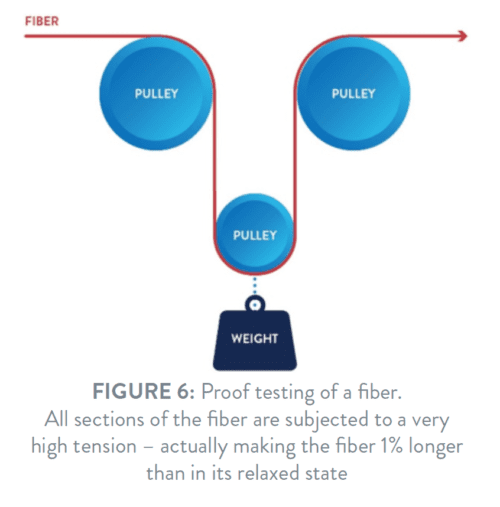
The proof test itself is simple. Fiber is typically guided around a pulley with a 1 kg weight attached to it for 100 kpsi proof test (Figure 6).
Fibers for use in submarine cables are normally proof tested even more stringently (2% elongation) to ensure even better lifetime performance.
An undamaged fiber which is proof tested 1% (100 kpsi) and used in standard applications and cable constructions will have a very long lifetime – typically 40 years or more. But fibers may get damaged. If that happens before proof testing, the fiber will break and the problem is eliminated.
However, damage to the fiber after proof testing may happen on rare occasions. Fibers are wound on spools for easy and safe handling and transportation and if the wound fiber “package” is somehow affected by a mechanical impact – as for example if the fiber spool is accidently dropped and hits the corner of a table – this may create large cracks in the fiber surface, and the fiber may suddenly not possess the expected strength anymore.
Likewise, the actual glass surface of the fiber may be “scratched” – potentially leaving large cracks in the fiber surface. Such scratches may have different causes but probably the most obvious of those causes is that the tool used to strip the coating of the glass fiber may inadvertently inflict scratches on the fiber surface. Also, sharp small objects may penetrate the fiber coating if the fiber is being forced against them – again possibly scratching the fiber glass surface.
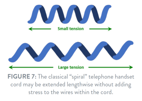
In “loose tube” cable constructions fibers are placed in plastic tubes, which are helically wound around the cable-core. Such a helical construction ensures that cables may be pulled – and thereby elongated – quite a bit during installation before strain is transmitted to the actual fibers. The effect is the same as seen in a classical “spiral” telephone handset cord which can be extended quite a long way without putting additional strain on the copper wires within the cord.
Most cable constructions are similarly able to “absorb” significant strain on the cable before transmitting any additional strain to the fibers themselves, and in general such a “maximum pulling force” is always specified for cables – although different names may be used for it.
Nevertheless, a small risk does exist if for example heavy machinery stretched sections of a cable so much that the actual fibers were unintentionally subjected to excess tension, leading to fast growth of cracks in the fiber surface. As a result, the fiber lifetime may have been reduced – possibly without leaving traces on the cable or the fiber themselves. With modern equipment, training and knowledge, fiber damage problems are, however, highly uncommon.
In some situations, thermal variances may result in the movement of cables relative to the closures, and that may put the fibers under additional tension from time to time.
Because of helical structures present in many cable constructions the fiber is effectively situated in large diameter bends along the full cable length. Furthermore, it is common practice to coil a small amount of excess fiber in 50 mm or 60 mm coils in splice cassettes. So, in reality, the fiber is almost always under constant – but small – stress during its operational lifetime. Since the bending diameters are typically large the resulting lifetime for an un-damaged fiber is still very long. The breaking risk of a high-quality fiber under such conditions is therefore negligible. A very important feature for cables carrying signals to thousands of users.
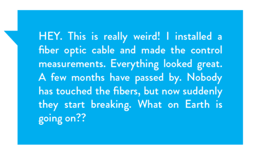
For a damaged fiber, however, a rather puzzling situation may arise. The fiber may be fully installed, control measured, and all parameters may appear to be fine. However, because of damage the fiber may contain rather large cracks, which may propagate and hence weaken the fiber. Even with commonly used cable constructions and splice cassettes, damaged fibers may break rather quickly. It’s possible that fiber breaks can start appearing months after installation when everything appeared to be in order at the time of installation and even when nobody has actually touched the fibers since.
Some fiber cables are specifically intended for applications where small bending diameters are required. This could be drop cables to cell towers or 5G small cells – and in particular cables intended for installation in homes and apartments where it is important to be able to route the cable closely around door frames, windows and ceilings in order to make the cable as invisible as possible. Cables as thin as 0.6 mm are available, which may be bent with a radius as tight as 2.5 mm, while maintaining a failure risk which is still much smaller than that of typical electronic consumer equipment.

In figure 8) the results of a typical lifetime test are shown. The test registers the lifetime of a high-quality fiber when that fiber is bent at different diameters. What is important to notice is that lifetime is hugely dependent on the bending radius. For the fiber in the test, the lifetime changes from 1 minute to 40 years by changing the bending radius from 1.0 mm to 1.8 mm. Although very long lifetime predictions tend to be somewhat questionable, it is obvious that a bending radius of 2.5 mm – like the one recommended for some ultra-bend insensitive fibers – will still give a very long lifetime.
However, rather than focusing on lifetime it may be much more interesting for the user to have a prediction of the number of expected failures over a reasonable period of time. For example, computer hard disk drives are often characterized by the Annualized Failure Rate (AFR) representing the expected average number of failures over one year. Some investigations have shown approximately 1% of such failures expected over a year.
To compare fibers with that, and using internationally recognized lifetime models, a fiber cable used inside an apartment with for example 12 quarter-circle bends of 2.5 mm radius will have an expected failure rate of 45 ppm over 30 years. That is 0.0045% failure risk over 30 years (not in just 1 year).
So, fiber optic cables in typical indoor home installations with bend radii as low as 2.5 mm still have exceptionally less failure risks than the typical electronic household equipment which we know and use in our daily life. And since a – very rare – fiber break will affect only a few users, the possibility of having almost invisible cable installations using thin cables and 2.5 mm radius bending outweighs the small risk of failure for many users.