
HOW TO SPEAK “FIBER GEEK” | ARTICLE 4: SINGLE-MODE FIBER GEOMETRIES
Leave a CommentWELCOME BACK, FIBER GEEKS!
The first Article in this series focused on growth in bandwidth demand and attenuation in optical fibers. Article 2 focused on several types of dispersion that exist in fiber, followed by Article 3 – Fiber strength and reliability.
This article, the fourth in the series, will focus on single-mode fiber geometries.
When speaking about fiber geometries, we typically consider diameters of core, MFD (Mode Field Diameter), cladding and coating. Also, the concentricities of those and the ovalities – and then the actual curl of the fiber. More on that later however.
The primary impact of fiber geometry occurs in the splicing and connectorization processes. Fibers with good and consistent geometry tend to splice and connect better with lower connectorization losses than do others. However, as highlighted previously in Article 2, fiber concentricity could also play an important role for polarization mode dispersion (PMD) performance and is an important parameter. For high quality fibers geometry has been good for a long time, and we may have been so accustomed to it that we sometimes take it for granted. However, this may not always be the case.
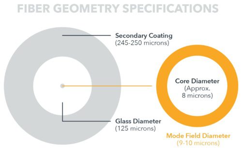
We’ll work our way through a typical fiber specification, highlighting the importance of various single-mode fiber geometry specifications. In the first figure we present the basic properties of the geometry of a fiber.
CLADDING DIAMETER (OUTER GLASS DIAMETER)
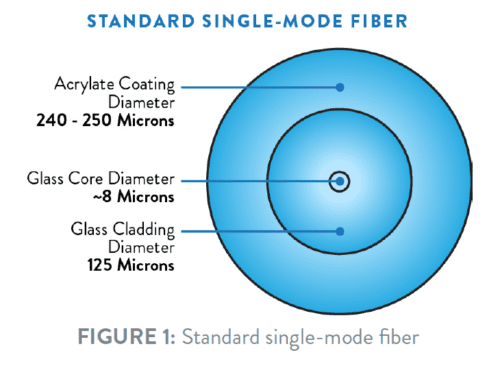
Cladding diameter is the outer diameter of the glass portion of the fiber. For telecommunications fibers, this diameter has been 125 microns (μm) for a very long time. On the other hand, the diameter tolerance has not always been 0.7 μm.
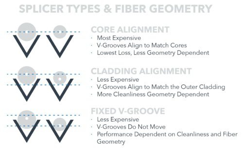
During the 1980s, optical fibers had outer diameter tolerances as high as +/- 3.0 μm. As illustrated in Figure 2, trying to match up 8 micron fiber cores when cladding diameters varied between 122 and 128 μm in diameter could result in very high losses, since the two cores may be significantly misaligned even though the claddings of the two fibers are perfectly aligned. This situation is why fusion splicing machines required additional technology to help align the actual fiber cores. This extra technology, however, increased the price of the splicing units.
As the industry matured, single-mode fiber diameters remained the same at 125 μm. However, over the same time period, the specification tolerance declined to 0.7 μm with typical variation along the length of the fiber becoming even tighter.
From a manufacturing perspective, such tolerances were not easy to achieve. When fiber was first invented, the developers had to create manufacturing methods along with ways to measure fiber diameter. When manufacturing to tolerances of tenths of a micron, inputs such as stray air currents, vibrations or particulate in the glass can cause significant diameter variability. These factors require top- tier fiber manufacturers to have very tight control over their processes and procedures.
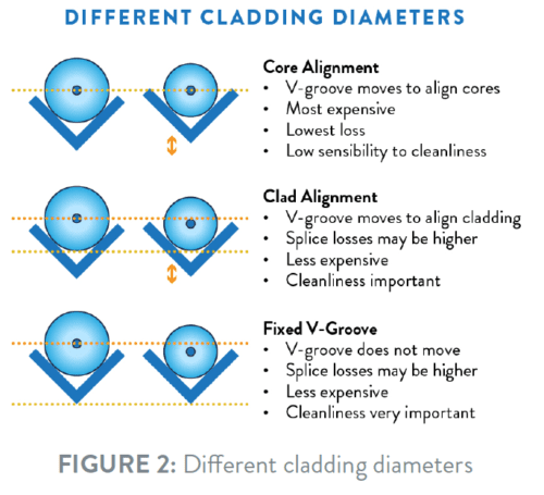
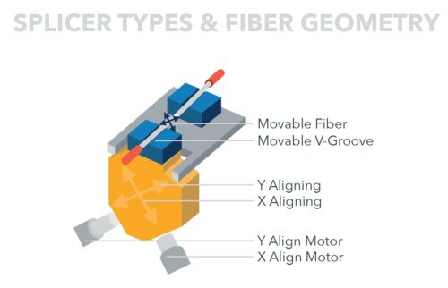
As diameter variability has decreased, splicing machines have reduced the alignment technologies needed. While there has been a significant decrease in the price of these machines, there has been no corresponding substantial increase in splice loss. Core alignment splicing machines still provide the best performance, however smaller “fixed V-groove” machines with lower prices and limited alignment capability have significantly reduced the performance gap. The typical splice loss for OFS AllWave®+ Zero Water Peak (ZWP) Optical Fiber, spliced using a core alignment splicing machine, is roughly 0.03 dB, whereas the same fibers spliced with a fixed V-groove machine have an average loss of approximately 0.05 dB. In a comparison of the absolute values, that is a significant difference. However, in the context of use in most fiber optic network applications, the difference is actually rather insignificant.
Enabled by tighter fiber geometry, the reduced cost of splicing machines is one of the factors that have contributed to the overall decrease in the cost of building fiber networks. In fact, this change has ultimately enabled fiber to the home to become a reality.
MODE FIELD DIAMETER (MFD)
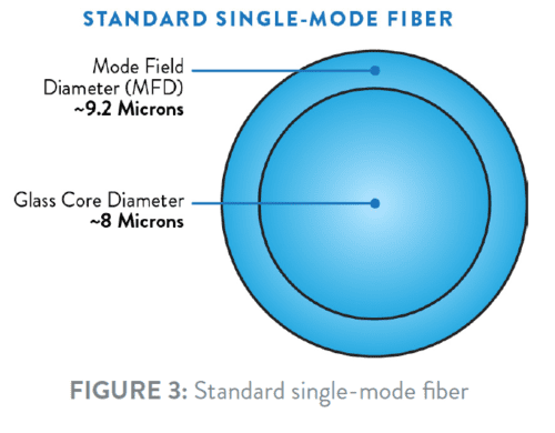
Mode field diameter (MFD) is another specification related to fiber geometry. In a typical G.652.D- compliant single-mode fiber, not all of the light travels in the core; in fact, a small amount of light travels in the fiber cladding. The term MFD is a measure of the diameter of the optical power density distribution, which is the diameter in which 95% of the power resides.
MFD is important for two main reasons.
The first reason is that fiber bending loss is typically correlated with MFD. Unless special fiber designs are used, as the MFD increases, bend loss also increases, and vice versa. Historically, fibers with smaller mode field diameters are less bend sensitive. That being said, modern fiber designs has enabled fiber manufacturers to make bend insensitive, single-mode fibers with a nominal mode field diameter of 9.2 μm – which is the same as the vast majority of classical standard G.652.D fibers. However, there are also fibers with MFD as high as 8.6 micron offering superior bending performance, with very low bending losses even for bending diameters as low as 5 mm – which is half of the smallest bending diameter specified by ITU-T for G.657.B3 fibers.
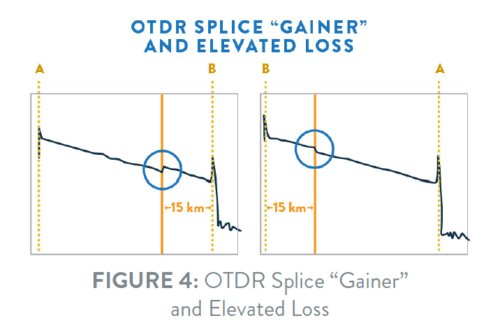
Second, because of the ease of use, OTDR measuring instruments are often used to measure attenuation. However, OTDRs only give correct results if the measurement conditions are perfect. A sudden jump in MFD is definitely not a perfect measurement condition. So in the case where two fibers of different mode field diameters are spliced together, the OTDR will errantly show either a power gain, known as a “gainer”, or elevated loss, depending on in which direction the measurement is taken. When measured from the larger MFD into the smaller, a gainer is produced. When measured from the smaller MFD into the larger, an elevated loss is seen, as shown below. This is an artifact of the OTDR measurement method and does not affect transmission properties. Breaking and re-splicing the fibers will typically not change the result, unless there’s a bad cleave or some other anomaly at the splice interface. The correct way to measure splices overall is bi-directional OTDR, which is even more important for fibers with MFD mismatches.
This fact shows why it may be advantageous to use bend-insensitive fiber with MFDs of 9.2 micron. Since experience with installation and measurements of fibers is almost always gained working with standard G.652.D fibers with MFDs of 9.2 micron, such bend insensitive G.657 fibers will behave in a very familiar way in terms of splicing and control measurements. Especially when splicing to the installed base of 9.2 μm MFD single-mode fiber.
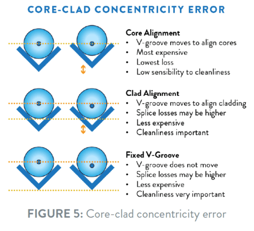
CORE-CLAD CONCENTRICITY ERROR
Core/clad concentricity error (CCCE or CCE) is also called Core-Clad Eccentricity and measures how well the core is centered in the fiber. CCCE is measured in microns and, of course, the closer the core is placed to perfect center, the lower the CCCE value and the better it is. Again, core aligning splicers tend to give the lowest splice losses.
CLADDING NON-CIRCULARITY
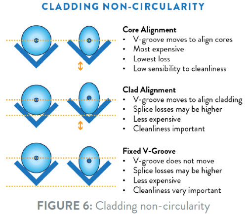
Clad non-circularity is also called Cladding Ovality and measures a fiber’s deviation from being perfectly circular – becoming an oval rather than a circle. It is measured as a percentage difference between the “long” and the “short” diameter of an oval. If the Cladding Non-Circularity is zero the cladding forms a perfectly round circle. Similar to other fiber properties, better cladding non-circularity can result in improved splicing and connectorization performance.
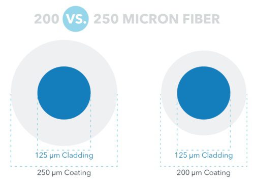
FIBER COATING
While coating specifications are not as stringent as glass specifications, they are also important – especially when fibers are used in ribbons. The two main parameters are Coating Diameter (Uncolored) 237 – 247 μm and Coating-Clad Concentricity Error of max. 0.5 micron.
For roughly the first 30 years of single-mode fiber manufacturing, a coating nominal diameter of approximately 245-250 μm was standard in the industry. However, in 2014, OFS launched a 200 μm fiber in response to the need for higher fiber density in fiber optic cable designs.
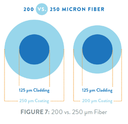
Although the difference between 200 and 250 μm is not tremendously large, smaller diameter fibers can enable twice the fiber count in the same size buffer tube in a cable, while also still preserving long-term reliability. This fact has led to many new compact cable designs, including extremely small micro-cables, loose tube duct cables and all-dielectric, self-supporting (ADSS) aerial cables. As the demand for higher fiber density continues to increase, we can expect to see even more cable designs taking advantage of smaller diameter coatings. Important though, is that the coating will still be able to sufficiently shield the fibers from micro-bending, which may otherwise cause increased losses in the fiber when the fiber is inadvertently being “squeezed” in the cable – especially with low temperature.
Another possibility is to make the glass fiber itself less sensitive to such potential problems – so it’s not just a simple task of reducing the thickness of the fiber coating, but obtaining a sufficiently good fiber performance too.
Besides inherent size, coating diameter control is extremely important. Coating diameter can affect the size of the overall bundle in fibers. If the coating is too thick, the overall bundle may incur strain sooner than expected. If, on the other hand, coating concentricity is not good, there can be additional concerns particularly when splicing ribbons.
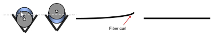
FIBER CURL
The final parameter we will discuss is fiber curl.
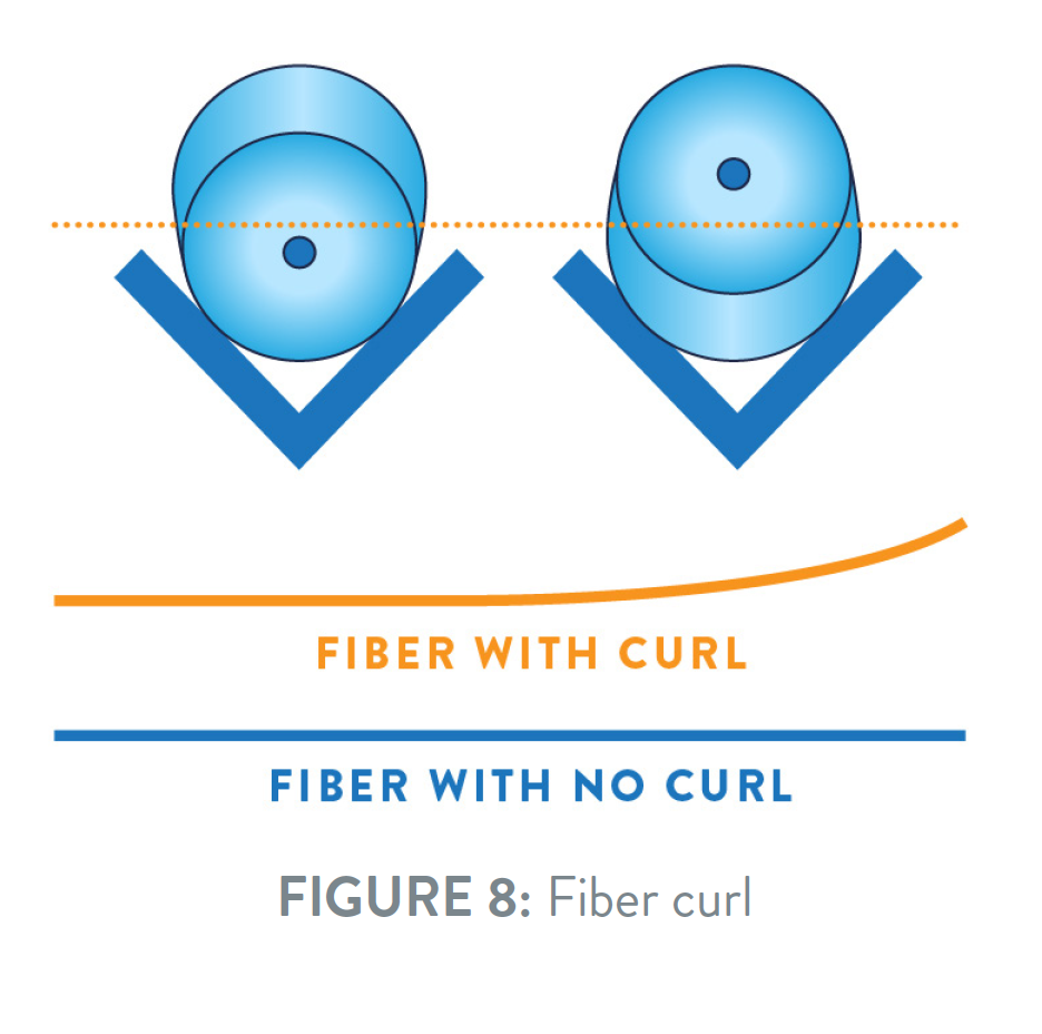
Fiber curl assesses the non-linearity of bare glass. In other words, fiber curl measures how straight the glass fiber is when no external stressors are present. If imbalanced stresses are frozen into a fiber during the draw process, curl can result. This curl can show up during the splicing of fiber optic ribbons or when fixed V-groove splicing machines are used.
If curl occurs, the two ends of the fiber will not be straight or match up during the splicing process. This situation leads to both high losses and difficulty splicing. Curl is measured in meters of curl, with a typical specification being > 4m. When optical fiber comes out of the fiber draw, it is annealed during the manufacturing process to reduce the effects of curl. As a result of this process, for users of top-quality fiber, fiber curl poses no concern for typical telecom applications.
Fiber geometry is often taken for granted by end users, primarily because it has been very good for so long. However, it has taken hard work and the contributions of innumerable people over many years for fiber geometry quality to reach its current level.

 OFS expanded its ocean product portfolio by introducing the new TeraWave SCUBA 125 Optical Fiber at the OFC Conference in San Diego, California, held March 12-15.