
This article focuses on the parameters that affect available bandwidth in optical fibers, and the dispersion mechanisms of various fiber types and non-linear effects. Dispersion describes the process of how an input signal broadens out as it travels down the fiber. There are several types of dispersions that we will cover. We’ll also take a cursory look at other important nonlinear effects that can reduce the amount of bandwidth that is ultimately available over an optical fiber.
Dispersion
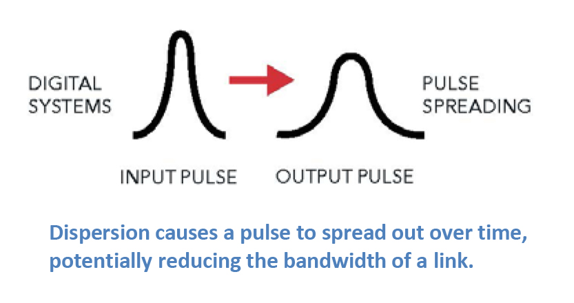
Most of the traffic traveling through fiber networks takes the form of a laser pulse, where the laser is pulsed on and off, effectively forming a digital square wave comprised of “1”s and “0”s. Dispersion causes a pulse to spread out over time, effectively rounding the edges, and making it harder for the detector to determine whether a “1” or a “0” is being transmitted. When this happens, the effective bandwidth of the link is reduced. The three main types of dispersion mechanisms are modal dispersion, chromatic dispersion, and polarization mode dispersion. Because these mechanisms affect fiber networks in different ways, we’ll discuss each in some depth. Please download the full article for more information.
Modal Dispersion
In general, our article on Single-Mode Optical Fiber Selection focuses on single-mode fibers since they comprise the vast majority of fiber kilometers deployed around the world. In contrast to multimode fibers, single-mode fibers are used for all high-capacity, long-distance networks due to their low attenuation and high bandwidth. A main limiting factor of multimode fibers is modal dispersion.
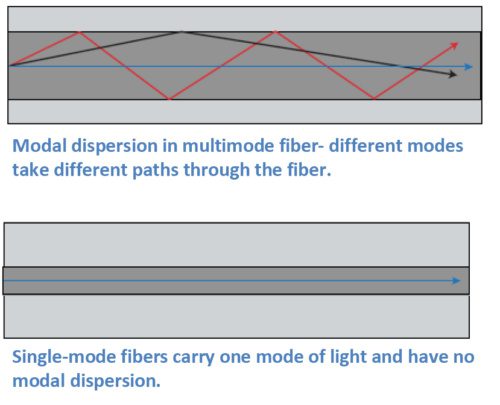
Multimode fibers carry multiple modes of light at the same time. While a mode of light can be thought of as a ray of light, a typical multimode fiber can have up to 17 modes of light traveling along it at once. These modes all traverse slightly different paths through the fiber, with some path lengths longer than others. Modes that take a straighter path will arrive sooner, and modes that bounce along the outer edges of the core of the fiber take a longer path and arrive later. The effect on the end pulse is called modal dispersion, since it is due to the different modes in the fiber. Multimode fibers are designed to reduce the amount of modal dispersion with precise control of the index of refraction profile, through the quantity of dopants used in the core. However, it isn’t possible to completely eliminate modal dispersion in multimode fibers.
Chromatic Dispersion
Chromatic dispersion describes a combination of two separate types of dispersion, namely material dispersion and waveguide dispersion. Light travels at different speeds at different wavelengths, and all laser pulses are transmitted over a wavelength range. Light also travels at different speeds through different materials. These varying speeds cause pulses to either spread out or compress as they travel down the fiber. Fiber designers can use these two points to customize the index of refraction profile to produce fibers for different applications. Chromatic dispersion isn’t always a bad thing. In fact, it can be used as a tool to help optimize network performance.
For example, the first lasers used for fiber transmission operated at 1310 nm, and many networks still use that wavelength. Fiber designers therefore developed the first single-mode fibers to have minimum or zero dispersion at this wavelength. In fact, G.652 fibers are still designed this way. In these fibers, dispersion is higher in the 1550 nm window.
Today’s networks often operate with multiple wavelengths running over them. In these networks, nonlinear effects that result from the multiple wavelengths can affect network operation. We’ll give a brief overview of some of these non-linear effects in this article. Chromatic dispersion is often used as a tool to help optimize these types of networks.
Polarization Mode Dispersion (PMD)
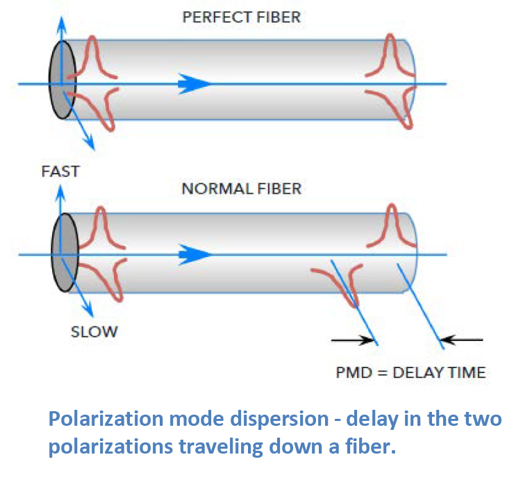
Light is an electromagnetic wave and is comprised of two polarizations that travel down the fiber at the same time. In a perfectly round fiber deployed with perfectly balanced external stresses, these polarizations would reach the end of the fiber at the same time. Of course, our world isn’t perfect. Even small amounts of glass ovality/non-concentricity or non-concentric stresses in the cable can cause one of the polarizations to travel faster than the other, spreading out in time as they travel along the fiber. This phenomenon is called polarization mode dispersion (PMD).
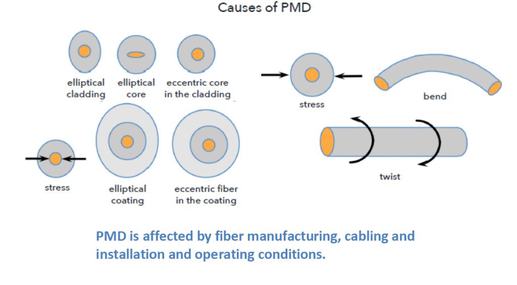
Cabling and installation affect PMD, and even things like vibration from trains moving down tracks or wind-induced aerial cable vibrations can affect PMD. However, the impacts of these interactions are typically smaller than the inherent PMD caused by the glass manufacturing process.
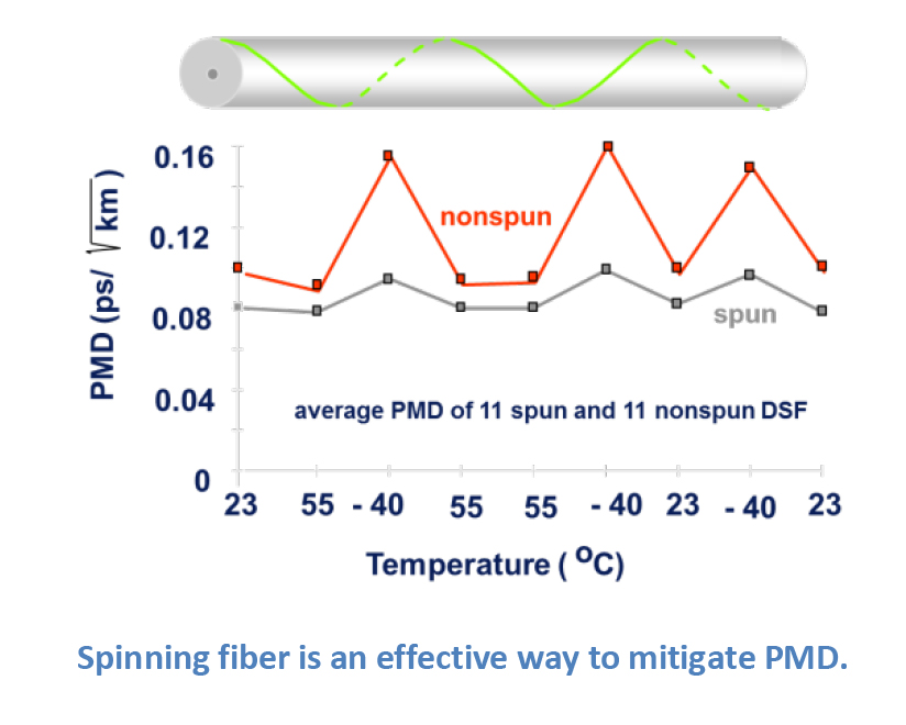
There are ways to mitigate PMD. One very effective method is to make the glass fiber as geometrically round and consistent as possible. OFS uses a special technique to accomplish this. Using a patented process called fiber “spinning”; half-twists are translated through the fiber during the draw process, reducing the non-concentricities and ovalities in the glass that are the major contributors to increased PMD.
Non-Linear Effects
There are a host of other factors that network, equipment, and fiber designers have needed to consider as network capabilities have grown over the years. These factors often result as we collectively add more and more wavelengths of traffic at greater speeds and higher power levels.
It is not the intent of this article to review each of these in depth, but instead to touch on them so the reader can have a passing familiarity. The highest profile of these factors is four-wave mixing, which led to the development of non-zero dispersion-shifted fibers (NZDF). However, other non-linear effects include self-phase modulation, cross-phase modulation, Raman and Brillouin scattering, and others. As mentioned earlier, chromatic dispersion can be used to offset the effects of four-wave mixing. For those non-linear effects related to higher power levels, increasing the effective area where the light travels down the fiber can help to reduce the impact of these other non-linear effects.
Dispersions and non-linear effects are the least understood issues in the general fiber user population, mainly because the guidelines used to match up today’s fibers and electronics typically work so that the end user doesn’t need to have a detailed background to bring up a system.
OFS has multiple decades of experience with fiber optic networks. Please contact your local OFS representative if you would like additional information regarding any of the items in this article.
OFS is a market leader in the design and manufacture of standard and custom Dispersion Slope Compensating Modules (DSCMs) also known as Dispersion Compensating Modules (DCMs). Our fixed broadband, reconfigurable, and tunable colorless modules round out a product line that is well-suited for the major transmission fiber types.