We use cookies to help us provide you with a more enhanced and personalized experience adapted to your interests. By using our site you agree to our Terms of Use and Privacy Policy, including our use of cookies.
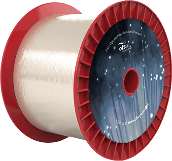
HCS® Industrial Graded-Index and Step-Index Fiber Optic Cable Selection Guide
Indoor and outdoor optical fiber cables for use in Substation Automation, Factory Automation, Industrial Ethernet, HVDC Systems, and Power Electronics.
When you’re trying to decide on which fiber optic cable to choose for an application. You have many choices of various constructions and fiber types of as has made this step easier for you. With the help of our new cable selection guide, which consists of cables for industrial applications, what the selection guide is designed to do is to make your job easier to determine the most appropriate and cost-effective cable for your project or installation. The selection guide is going to focus on the office industrial multimode fiber optic cables that are designed for, and common in, many factories and substations, as well as other harsh environment applications.
For those of you who work in industrial environments, whether it be a steel mill, paper mill, a substation, or any type of harsh environment, the HCS product line is ideal for you for many reasons. Unlike traditional fibers, the primary fiber coating makes bonds to the fiber and enhances the strength during the draw or production process. Additionally, because the coating remains on the glass during the termination process, the fiber maintains its inherent strength. This makes it unique in that there is never bare glass exposed to the environment such as humidity, dirt, and dust. Those environmental factors are all known to detract from the strength of the fiber optics. When you’re considering the product line, here’s what you’re getting a rugged and robust construction resistance to abrasion in industrial chemicals. Reliable and repeatable termination process. A short learning curve for terminations. So selection considerations include extreme temperatures of Florida, Arizona, to the frigid temperatures of the Canadian tundra or Alaska. Humidity also plays a factor in states like Texas and Louisiana. You will also consider installation pull strength, the compressive strength of the cable. What kind of weight can the cable bear during the installation?
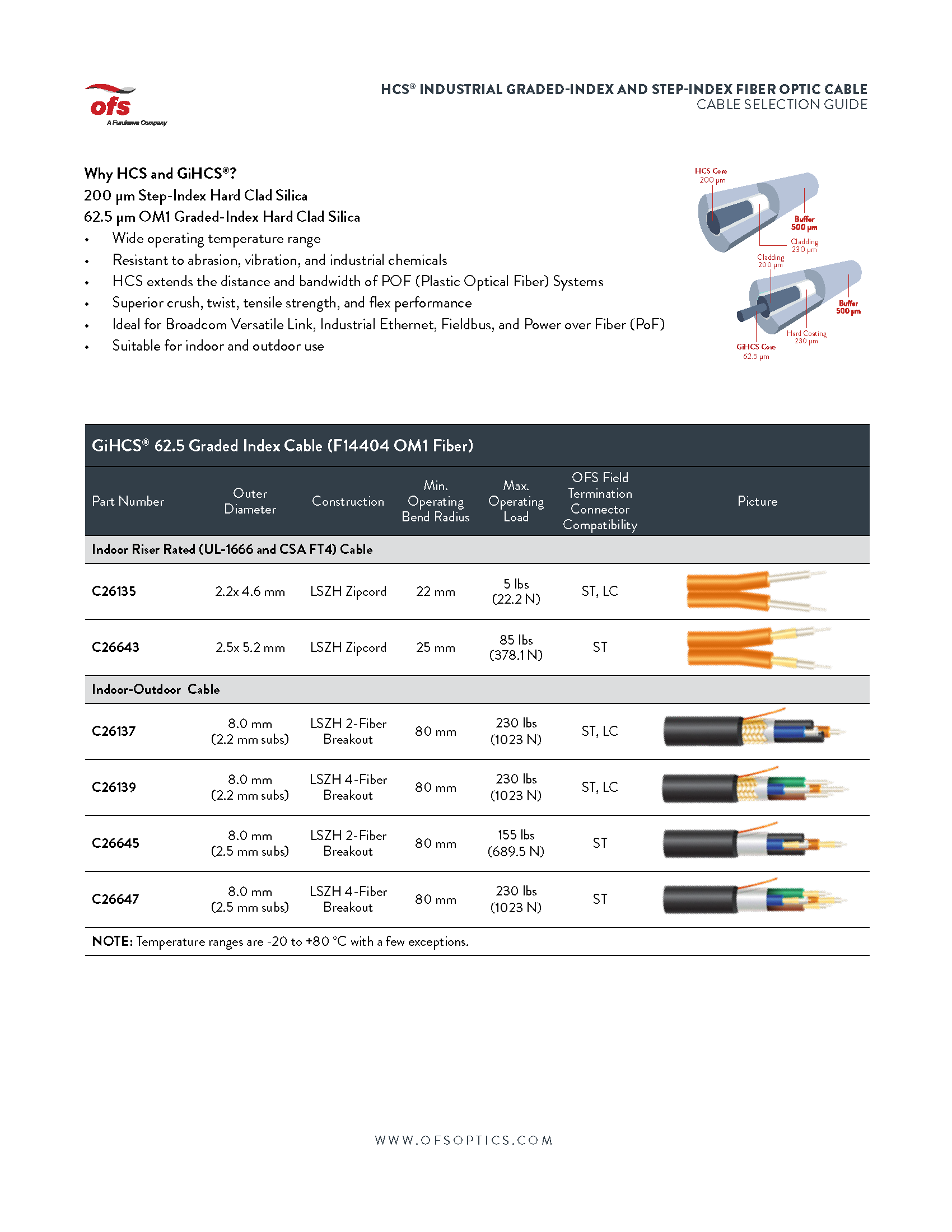
The first page here we have 62.5 micron cables, which are indoor zipcord cables for data center type applications. Indoor outdoor cables which can be used for either these are breakout cables and all the outdoor cables will have a water block in the cable as well as some of them will have a glass armor for road and deterring because you’re going to deter the road they’re trying to chew through the cable.
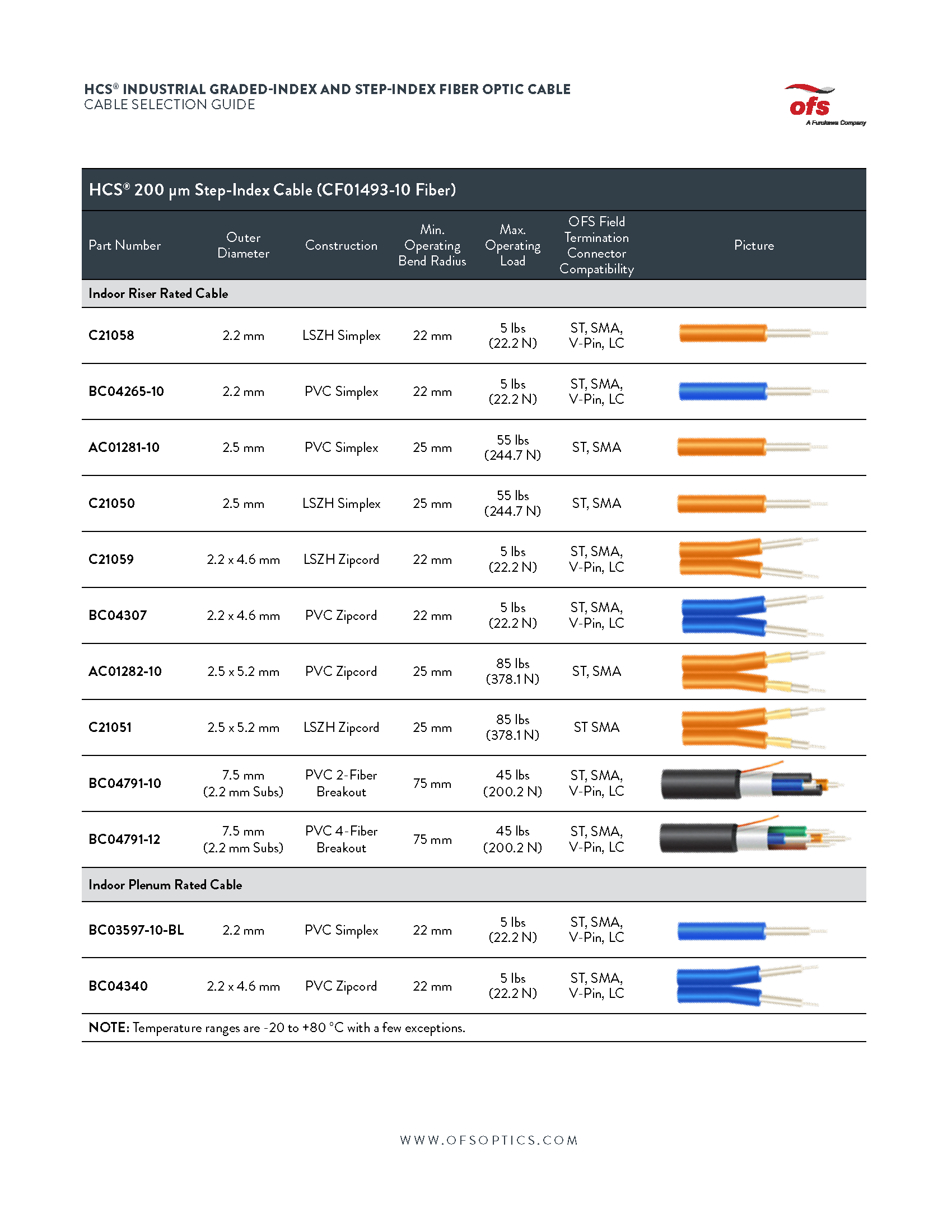
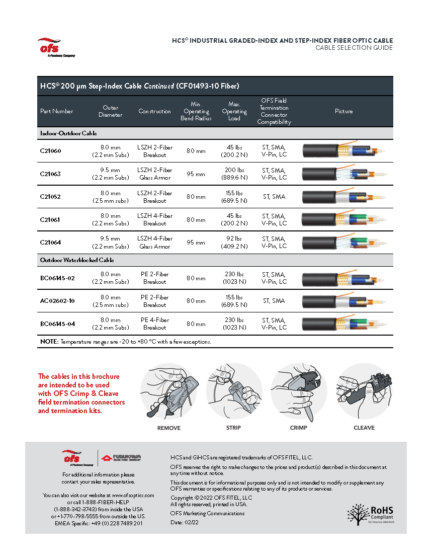
And looking at our 200 micron step index cable from simplex to zip cords to breakouts through indoor applications, we have riser rated we have plenum rated, we have indoor outdoor cables. And we also have cables that are designed strictly for outdoor applications. Again, with the water block, as you see at the bottom here, we have a schematic which shows the termination process of a typical O of this connector.
First, we’re going to remove the cable jacket, then we’re going to strip the fiber. Then we’re going to crimp the connector on, and then we’re going to cleave the glass. And for a pristine finish on the end of the connector. What I’ll do in my next talk is share with you information on the connector systems that go along with the cables we just talked about. And that’s what’s new in my world.
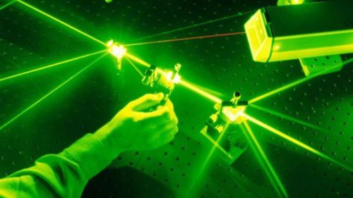
Article 1 in this series focused on growth in bandwidth demand and attenuation in optical fibers caused by bending, and the built-in mechanisms scattering and absorption. Article 2 focused on several types of dispersion that exist in fiber.
This article, the third in the series, will focus on fiber strength and reliability.
FIBER RELIABILITY
Except for products specifically intended for short time use only, lifetime and durability are normally of rather high importance for the user. As for optical fibers, the installation of the cabled fibers is typically both time consuming and very costly, and so reliability and lifetime may be even more important.
Historically this has resulted in a lot of focus on fiber lifetime, and although materials for optical fiber manufacture have been under constant improvement over the last 30 – 40 years, the longevity of even some of the first fiber optic cables is impressive.
Unlike most other fiber properties, we are here dealing with statistical properties which are difficult and time consuming to measure, and the exact lifetime of an individual fiber cannot be predicted.
As such this is not different from lifetime considerations for other products, but failure consequences may typically be more severe.
Fiber has a reputation for excellent reliability, and that hasn’t been acquired by luck. For most end users, fiber just works, and they don’t give the topic much thought. However, this performance is based on a deep understanding of the mechanical performance of the glass to the molecular level. Researchers have spent entire careers acquiring this understanding and translating this knowledge to product design, manufacturing, and installation recommendations.
WHY DO FIBERS BREAK?
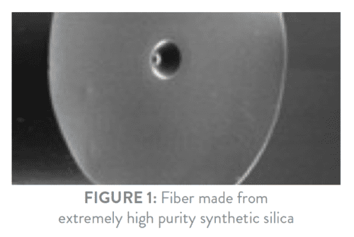
For starters, pristine glass optical fiber is stronger than steel, when measured diameter to diameter. Although the actual intrinsic strength of glass can vary according with sample preparation, it is often greater than 700,000 pounds/square inch (PSI), compared to 70,000- 85,000 PSI for cold rolled steel.
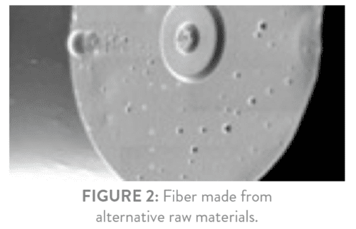
Although glass is very strong, it is brittle so it cannot be stretched for large amounts without breaking. Imperfections and mechanical flaws may weaken the glass significantly as may impurities even as small as fractions of a micron.
In order to limit the number of impurities to an absolute minimum, OFS use synthetic silica to make our glass. Synthetic silica (SiO2) is hence made from ultra-pure chemicals which are pure to the parts per billion level, and the actual core of the fiber is pure to the 10 parts per trillion level. It would resemble allowing only one bad rice-grain in a 20 ft standard shipping container filled with good rice. By keeping such an extremely high glass purity, the risk of fiber weakening because of impurities is minimized. Other manufacturing methods may not provide similar high purity of the finished glass fiber.
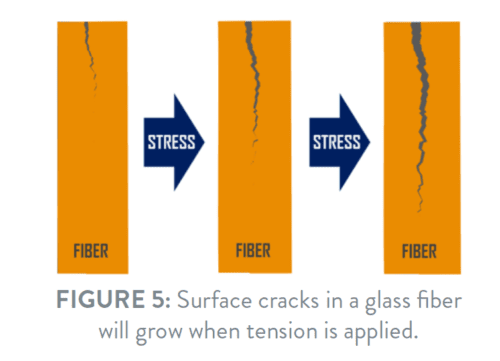
But impurities are not the only reasons that may cause a fiber to break. A glass surface typically contains a number of cracks of different sizes. This is true for fiber glass surfaces as well, and when stress is applied to the fiber, the cracks will grow larger. As might be expected, a large stress on the fiber will cause fiber cracks and other flaws to grow more rapidly than if only a small stress is applied to that fiber.
There may be a huge difference in the speed by which the cracks grow, and this may not always seem obvious. More on that later.
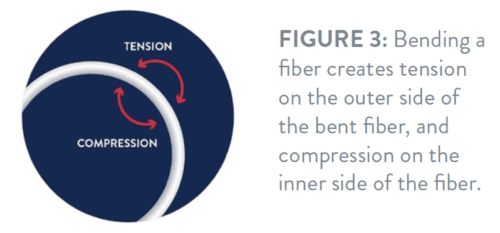
Another issue which may not seem obvious is that stress is also applied to a fiber simply by bending that fiber. As shown in Figure 3 the outermost surface of a fiber bend will be stretched and result in tension – whereas the innermost surface will be compressed. Compression does not cause cracks in the fiber surface to grow larger – but tension does.
It probably seems more obvious that tension applied along the length of the fiber (typically by pulling the fiber) will also cause cracks and flaws to grow.
When cracks or flaws grow larger the strength of the fiber is reduced because a smaller cross section of the fiber is now holding the fiber together. So, a fiber with large cracks or flaws will break at a lower strain than a pristine fiber containing only small (or no) cracks.
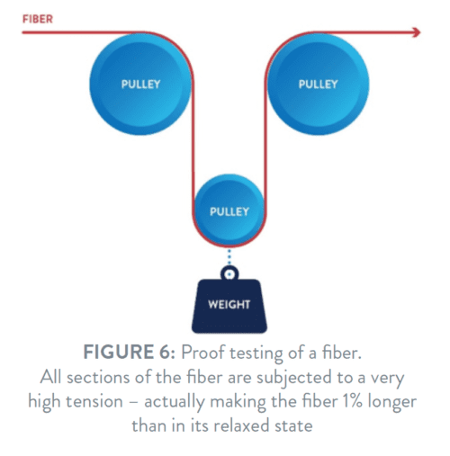
To ensure that no large cracks or flaws are present in the fiber, a manufacturing step called “proof testing” is added after the actual making of the fiber. During proof testing, every 1 – 2 meter section of the fiber is subjected to a relatively large strain. So large that it makes the fiber 1% longer. Under such large strain cracks and flaws in the fiber will grow quickly, and if the cracks are large enough the fiber will simply break. This ensures that after proof testing no large cracks or flaws exist in the fiber anymore. However, small cracks and flaws will still be present and that is why the glass production method is so important. The purer the glass, the less likely problems will occur long term.
The proof test itself is simple. Fiber is typically guided around a pulley with a 1 kg weight attached to it for 100 kpsi proof test (Figure 6).
Fibers for use in submarine cables are normally proof tested even more stringently (2% elongation) to ensure even better lifetime performance.
An undamaged fiber which is proof tested 1% (100 kpsi) and used in standard applications and cable constructions will have a very long lifetime – typically 40 years or more. But fibers may get damaged. If that happens before proof testing, the fiber will break and the problem is eliminated.
However, damage to the fiber after proof testing may happen on rare occasions. Fibers are wound on spools for easy and safe handling and transportation and if the wound fiber “package” is somehow affected by a mechanical impact – as for example if the fiber spool is accidently dropped and hits the corner of a table – this may create large cracks in the fiber surface, and the fiber may suddenly not possess the expected strength anymore.
Likewise, the actual glass surface of the fiber may be “scratched” – potentially leaving large cracks in the fiber surface. Such scratches may have different causes but probably the most obvious of those causes is that the tool used to strip the coating of the glass fiber may inadvertently inflict scratches on the fiber surface. Also, sharp small objects may penetrate the fiber coating if the fiber is being forced against them – again possibly scratching the fiber glass surface.
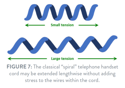
In “loose tube” cable constructions fibers are placed in plastic tubes, which are helically wound around the cable-core. Such a helical construction ensures that cables may be pulled – and thereby elongated – quite a bit during installation before strain is transmitted to the actual fibers. The effect is the same as seen in a classical “spiral” telephone handset cord which can be extended quite a long way without putting additional strain on the copper wires within the cord.
Most cable constructions are similarly able to “absorb” significant strain on the cable before transmitting any additional strain to the fibers themselves, and in general such a “maximum pulling force” is always specified for cables – although different names may be used for it.
Nevertheless, a small risk does exist if for example heavy machinery stretched sections of a cable so much that the actual fibers were unintentionally subjected to excess tension, leading to fast growth of cracks in the fiber surface. As a result, the fiber lifetime may have been reduced – possibly without leaving traces on the cable or the fiber themselves. With modern equipment, training and knowledge, fiber damage problems are, however, highly uncommon.
In some situations, thermal variances may result in the movement of cables relative to the closures, and that may put the fibers under additional tension from time to time.
Because of helical structures present in many cable constructions the fiber is effectively situated in large diameter bends along the full cable length. Furthermore, it is common practice to coil a small amount of excess fiber in 50 mm or 60 mm coils in splice cassettes. So, in reality, the fiber is almost always under constant – but small – stress during its operational lifetime. Since the bending diameters are typically large the resulting lifetime for an un-damaged fiber is still very long. The breaking risk of a high-quality fiber under such conditions is therefore negligible. A very important feature for cables carrying signals to thousands of users.
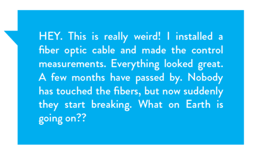
For a damaged fiber, however, a rather puzzling situation may arise. The fiber may be fully installed, control measured, and all parameters may appear to be fine. However, because of damage the fiber may contain rather large cracks, which may propagate and hence weaken the fiber. Even with commonly used cable constructions and splice cassettes, damaged fibers may break rather quickly. It’s possible that fiber breaks can start appearing months after installation when everything appeared to be in order at the time of installation and even when nobody has actually touched the fibers since.
Some fiber cables are specifically intended for applications where small bending diameters are required. This could be drop cables to cell towers or 5G small cells – and in particular cables intended for installation in homes and apartments where it is important to be able to route the cable closely around door frames, windows and ceilings in order to make the cable as invisible as possible. Cables as thin as 0.6 mm are available, which may be bent with a radius as tight as 2.5 mm, while maintaining a failure risk which is still much smaller than that of typical electronic consumer equipment.
In figure 8) the results of a typical lifetime test are shown. The test registers the lifetime of a high-quality fiber when that fiber is bent at different diameters. What is important to notice is that lifetime is hugely dependent on the bending radius. For the fiber in the test, the lifetime changes from 1 minute to 40 years by changing the bending radius from 1.0 mm to 1.8 mm. Although very long lifetime predictions tend to be somewhat questionable, it is obvious that a bending radius of 2.5 mm – like the one recommended for some ultra-bend insensitive fibers – will still give a very long lifetime.
However, rather than focusing on lifetime it may be much more interesting for the user to have a prediction of the number of expected failures over a reasonable period of time. For example, computer hard disk drives are often characterized by the Annualized Failure Rate (AFR) representing the expected average number of failures over one year. Some investigations have shown approximately 1% of such failures expected over a year.
To compare fibers with that, and using internationally recognized lifetime models, a fiber cable used inside an apartment with for example 12 quarter-circle bends of 2.5 mm radius will have an expected failure rate of 45 ppm over 30 years. That is 0.0045% failure risk over 30 years (not in just 1 year).
So, fiber optic cables in typical indoor home installations with bend radii as low as 2.5 mm still have exceptionally less failure risks than the typical electronic household equipment which we know and use in our daily life. And since a – very rare – fiber break will affect only a few users, the possibility of having almost invisible cable installations using thin cables and 2.5 mm radius bending outweighs the small risk of failure for many users.
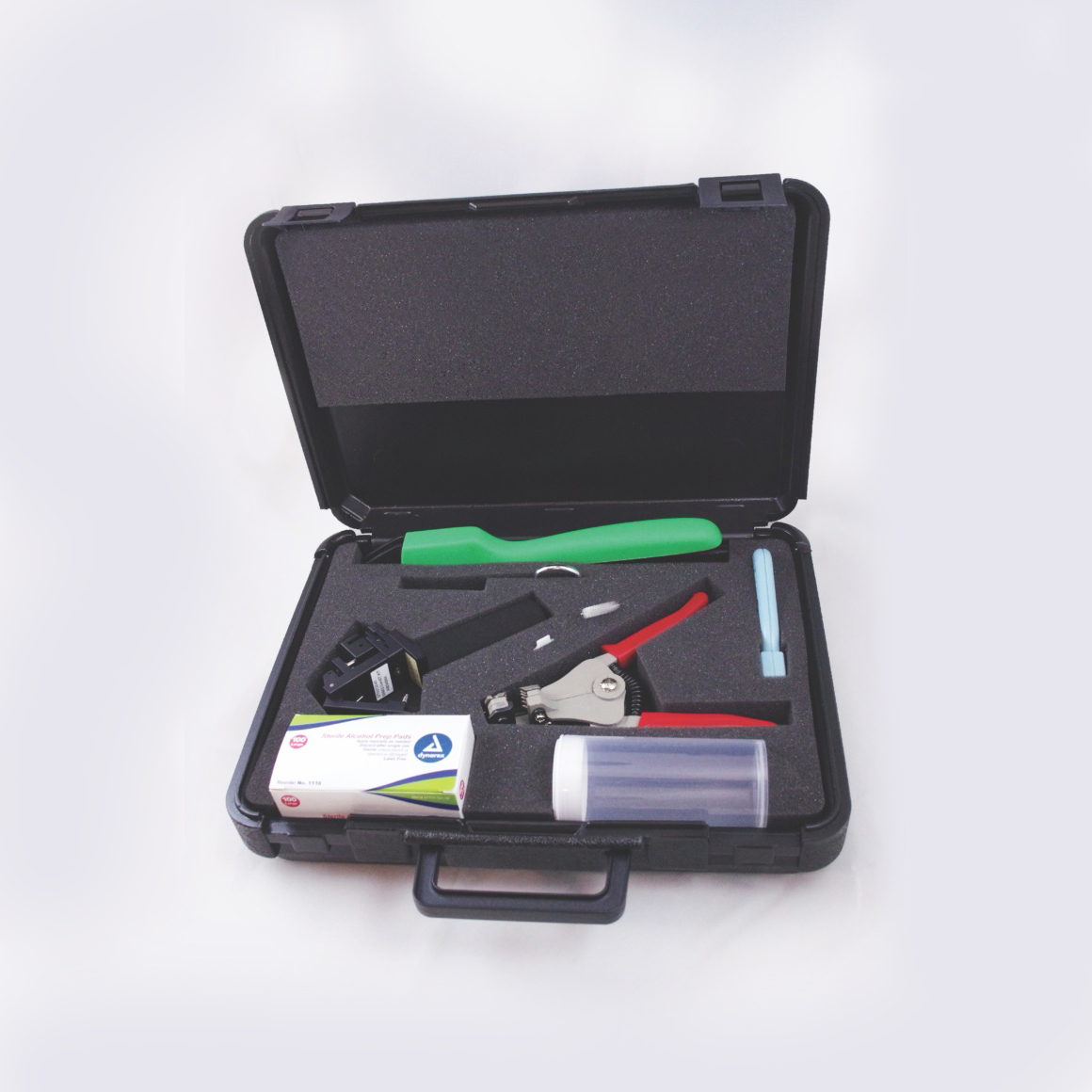
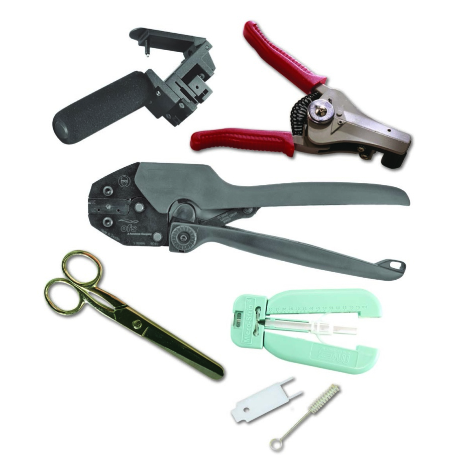
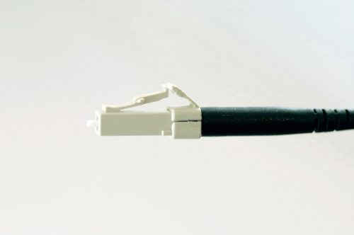
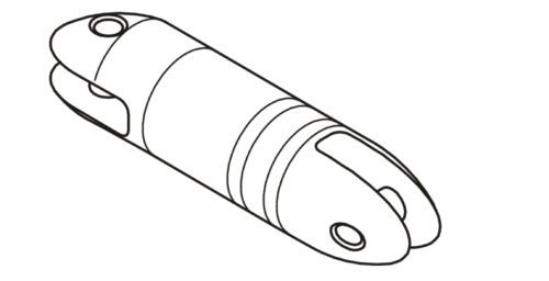
for 50 and 62.5 µm GiHCS®, 200 µm HCS® LC Connectors
Important Safety and Warranty Information
Please Read First!
Please make sure to READ and understand the termination instructions completely. Improper assembly will cause poor termination results and cause damage to termination kit components.
Make sure you WEAR eye protection during the termination process. Bare optical fiber is sharp and may splinter; handle very carefully and make use of the provided fiber optic shard disposal container.
For more information please CONTACT the sales representative in your region or call the factory for technical support:
Mon-Friday, 8:00 am-5:00 pm EST.
860-678-6636
770-798-5555 [Outside the USA and Canada]
Content
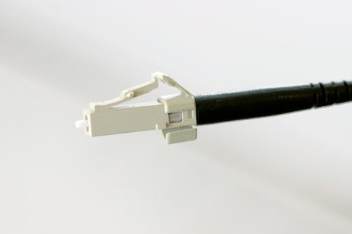
LC Termination Kit Contents
Related Products and Accessories (Sold Separately)
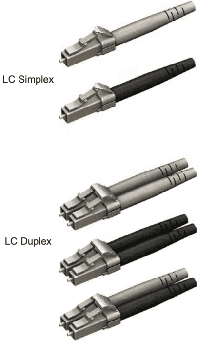
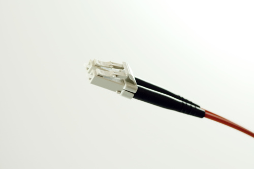
LC and LC Duplex Connectors
Insertion Loss Test Kit
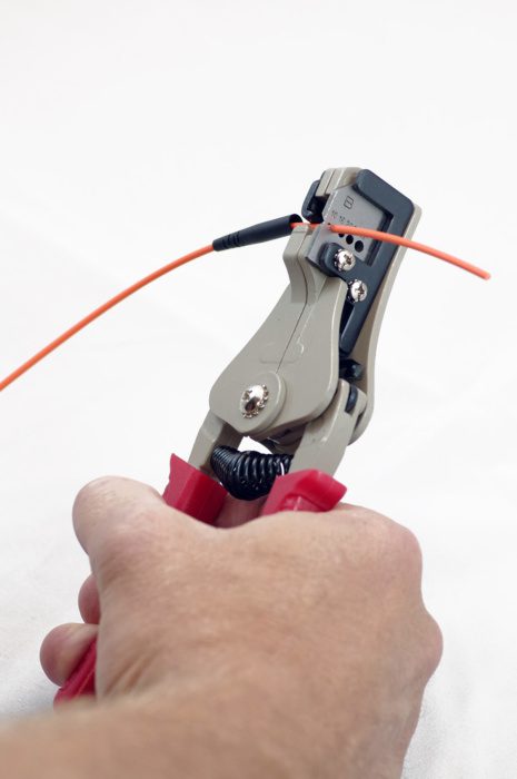
Slide STRAIN RELIEF BOOT (tapered end first) onto cable end and slide approximately 3 inches [76 mm] out of way.
STEP 2: Remove Outer Cable Jacket
Mark cable outer jacket 2.5 inches [63.5 mm] from cable end with a marker
Using 2nd hole (marked 1.6) from the open side of the cable jacket strip tool, remove the 2.5 inches [63.5 mm] of outer jacket.
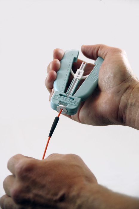
STEP 3: Remove ETFE Buffer
Insert the buffered fiber through the guide tube of the ETFE Buffer Strip Tool, all the way in until the cable jacket bottoms out inside it.
Holding cable securely, squeeze the tool’s handles to cut ETFE buffer then PULL STRAIGHT to remove the ETFE buffer.
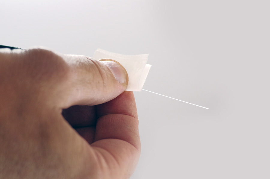
With alcohol prep pad folded in two, wipe the surface of fiber where the ETFE buffer was just removed.
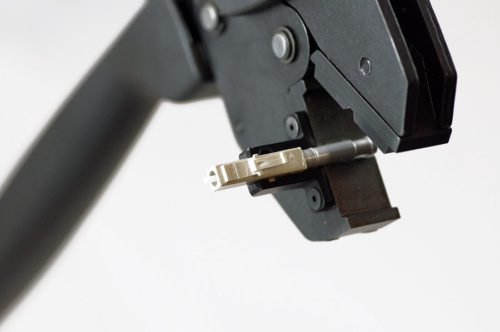
STEP 4: Install Connector Body
Locate the CONNECTOR BODY subassembly into the CRIMP TOOL nest as shown. Close the crimp tool handles lightly to secure connector in nest, but do not yet apply crimp
Insert stripped fiber into CONNECTOR BODY subassembly until the cable jacket bottoms out inside the connector
Squeeze handles of CRIMP TOOL to apply crimp. CRIMP TOOL will not release until fully crimped.
Remove CONNECTOR from CRIMP TOOL nest. Slide up and
install BOOT onto CONNECTOR.
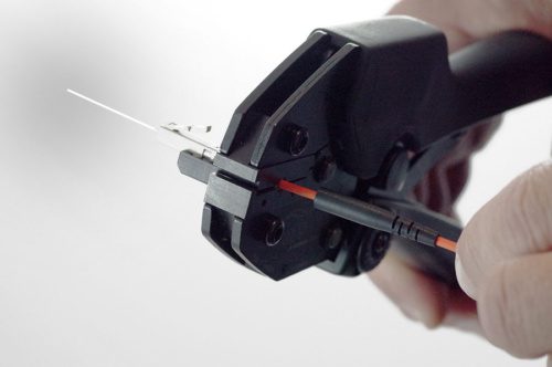
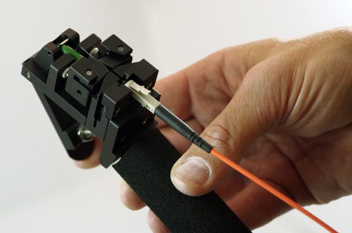
STEP 5: Cleave Optical Fiber
Holding the CLEAVE TOOL in a horizontal position, grip the handle while leaving your index finger free to actuate trigger
Gently insert CONNECTOR BODY into cleave tool as shown. Be sure to have it fully inserted and release the CONNECTOR BODY
Using index finger, slowly depress trigger to perform the cleave operation. The cleave process is complete when the optical fiber snaps away
from the connector. Do not release the trigger just yet!
Before releasing the trigger, remove CONNECTOR BODY from the
cleave tool and grasp the optical fiber scrap while releasing the trigger.
Gently remove the scrap fiber from the cleave tool while keeping it away from the tool’s diamond blade. Place the scrap optical fiber into the fiber optic shard container for safe disposal.
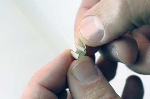
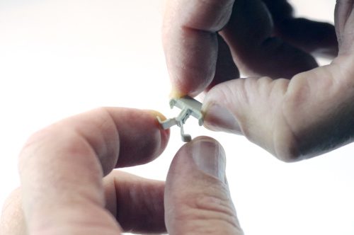
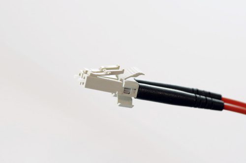
STEP 6: Install Anti-snag Latch or Duplexing Clip
Simplex Connector:
• Spread the clip slightly as shown.
• Install the clip around the connector, aligning as shown.
• Wrap around and snap on to secure.
Duplex Connector:
• Spread the clip slightly as shown.
• Install the clip around the connectors, aligning as shown.
• Wrap around and snap on to secure.
The PDF document also includes a Cleave Tool Cleaning Guide:
For cleaning your cleave tool, please order the OFS Cleave
Tool Cleaning Kit (part #P16247) which includes recommended cleaning fluid, swabs, and complete instructions.
The PDF document also includes a fiber optic troubleshooting guide for:
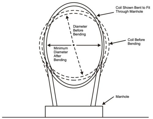
This document covers cable placing in conduit, innerduct, handholes, and manhole structures. The innerduct may be direct buried or placed in larger diameter conduits. In some applications, the innerduct may be lashed to an aerial strand.
This document covers conventional cable placing techniques that are used to pull or blow (cable jetting) the cable into the conduit or innerduct.
It is recommended that an outside plant engineer conduct a route survey and inspection prior to cable installation. Manholes and ducts should be inspected to determine the optimum splice locations and duct assignments. A detailed installation plan, including cable pulling or blowing locations, intermediate assist points, and cable feed locations should be developed based on the route survey.
2.2 Maximum Rated Cable Load
The maximum rated cable load (MRCL) for most OFS outside plant fiber optic cables is 600 lb; however, the cable documentation should always be checked because lower values of MRCL may apply for some cables. When using pulling equipment to install cable, measures should be taken to ensure that the MRCL is not exceeded. This includes the use of breakaway swivels, hydraulic pressure relief valves, and electronic tension control systems.
2.3 Minimum Bend Diameter
The minimum bend diameters for OFS cables are defined for both dynamic and static conditions. The dynamic condition applies during installation when a cable may be exposed to the MRCL, e.g., while pulling the cable around a sheave or capstan.
2.4 Temperature Limits
Storage and installation of OFS fiber optic cable is limited to the temperature ranges. Be aware that solar heating due to sunlight exposure can increase the cable temperature well above the ambient temperature.
3. Underground Optical Cable Precautions
Before starting any underground cable placing operations, all personnel must be thoroughly familiar with local company safety practices. Practices covering the following procedures should be given special emphasis:
Fiber optic cable is most often placed in a small-diameter innerduct rather than a large-diameter conduit. For existing conduit structures, multiple innerducts can be placed in a single conduit to provide multiple cable paths in the duct. Innerduct is also recommended because it provides a clean continuous path for the installation of the fiber optic cable.
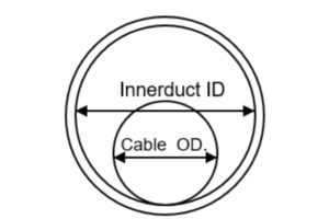
4.1 Diameter Ratio and Area Ratio
Diameter ratio and/or area ratio are used to determine the optimal cable OD that should be installed in an innerduct. Either ratio can be used, but consistently using one or the other is important to avoid confusion.
4.2 Direct Buried Applications
Studies have shown that vertical undulations in direct buried innerduct can greatly increase the required cable installation forces.
5. Cable Lubricant
Cable lubricant should be used when placing fiber optic cables. Recommended cable lubricants include Polywater4, Hydralube5, and similar cable lubricants that are compatible with polyethylene cable jackets. Both the winch line (or pulling rope) and the cable should be lubricated.
The backfeed technique is a common installation method that is used to divide the cable installation into two separate pulls. The backfeed technique may also be used near equipment offices when one end of the cable must be pulled by hand into the building, or at manhole locations where the cable route changes direction.
6.2 Forward-Feed Technique
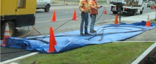
In the forward-feed technique, the leading end of the cable and excess cable length are pulled out of the innerduct at an intermediate manhole and stored on the ground in a figure-eight. This technique can be used multiple times during a cable installation to greatly increase the distance between cable splices.
6.3 Figure-Eight Installation Techniques
If figure-eight techniques are used during cable installation, the cable should be handled manually and stored on the ground. Place the cable on tarps to prevent damage from gravel, rocks, or other abrasive surfaces.
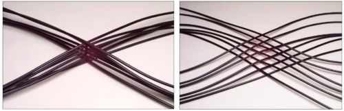
When figure-eighting heavy cables (264 fibers or more), the cable stack should be offset to prevent sheath dents and cable damage. Although sheath dents do not typically damage fibers, this type of cosmetic damage is undesirable. When utilizing the offset method, each crossover point of the cable stack should be offset about 2 inches instead of being stacked directly on top of each other.
Standard vs Offset Figure Eight
6.4 Handholes
Handholes are frequently used to provide access to cable splices and slack storage coils. On long cable pulls, handholes may be used to facilitate intermediate-assist placing operations. The intermediate-assist handholes are typically installed near obstacles or at a predetermined spacing that coincides with the maximum expected cable installation length.
7. Pulling Fiber Optic Cable
The following instructions assume general familiarity with outside plant cable placing procedures. They also assume that the innerduct is in place and a lubricated pulling tape or rope has been installed in the innerduct.
7.1 Feed Manhole
Breakaway Swivel Connector
Mount the cable reel on the reel carrier so that the cable feeds off the top of the reel. Position the cable reel adjacent to the manhole and in-line with the innerduct. The cable reel should be positioned close enough to the manhole so that excessive cable length is not dragging on the ground, but far enough away to maintain slack cable in the event of a sudden start or stop during the pulling operation. A distance of 10 – 15 feet is generally sufficient. Attach the pull line to the fiber optic cable using a cable grip and swivel connector. Caution: A breakaway swivel connector is required if a tension limited winch is not used to pull the cable.
7.2 Intermediate Manholes
The innerduct in intermediate manholes may be continuous through the manhole or it may be interrupted. In either case, the innerduct should be positioned in a straight path from entry duct to exit duct. If the innerduct is continuous and has been racked, remove the innerduct ties and straighten the innerduct through the manhole. If necessary, slack innerduct can be cut out using an innerduct cutter. Secure the innerduct in the manhole to prevent it from creeping into the main duct during cable placing operations.
OFS recommends the use of tension-limited winches for pulling fiber optic cable. The tension control may be accomplished by electrical, mechanical, or hydraulic methods. In any case, the tension-limiting device must be routinely calibrated as recommended by the equipment manufacturer. Cable winches that display cable tension but do not have automatic cutoff are not sufficient to protect the cable. If a tension-limited winch is not used, a breakaway swivel must be used to connect the fiber optic cable to the pulling line.
7.4 Capstan Winches
7.4.1 General
Breakaway swivels do not protect the fiber-optic cable after the cable pulling-eye passes the intermediate capstan winch; therefore, intermediate-assist capstan winches must be tension-limited. The capstan must also meet the minimum cable bend-diameters.
7.4.2 Set-up
The capstan winches should be positioned along the cable route where the expected pulling tension will be 600 pounds or less. Proper positioning of the capstans prior to the start of the pull will eliminate construction delays caused when an unplanned intermediate capstan assist must be added to the placing operation.
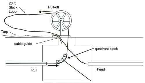
7.4.3 Slack Cable Loop
During the pulling operation, a slack loop of cable must be maintained on the pull-off side of the capstan as shown in Figure.
Intermediate Manhole Set-up
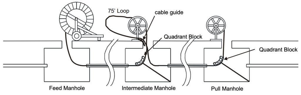
7.4.4 Adding Intermediate Capstans
If an intermediate capstan is added during the cable pull and the cable pulling eye has already passed through the manhole, a loop of slack cable must be pulled to the intermediate manhole before cable is wrapped on the capstan.
Adding an Intermediate Assist Capstan
7.4.5 Removing Cable from Intermediate Capstan Assist Winch
At the conclusion of the pull, the cable on the capstan is twist free. However, one twist per wrap will be generated in the cable if it is removed from the capstan and straightened.
8. Blown Optical Cable Installation
Cable blowing systems use high-pressure, high-velocity airflow combined with a pushing force to install the cable. A hydraulic or pneumatic powered drive wheel or drive belt is used to push the cable into the innerduct at the feed manhole. Controls and gauges on the cable blowing system allow the operator to monitor and adjust the air flow and push force that is exerted on the cable. Some cable jetting systems use a plug at the cable end to capture the compressed air and generate a small pulling force on the end of the cable.
9. Optical Cable Coiling
9.1 Coils Stored at Intermediate Holes
Many end users require that coils of slack cable be stored in intermediate manholes along the cable route. These slack storage coils are used for future branch splices or route rearrangements. It is important that the coiling method accommodates the proper coil diameter and does not introduce kinking or excessive twist into the cable.
9.2 Fold-Over Method
The Fold-Over Method is recommended for storing moderate lengths of slack cable. Form a cable bight and then twist the bight to form the first cable coil. Fold the coil over to form the second cable coil.
The teardrop coiling method is recommended for storing longer lengths of cable since it is easier to roll the cable than perform repetitive folding operations. The cable is stored twist free by rolling the cable bight in a manner similar to that used on the cable end.
9.4 Garden Hose Method
The garden hose method is recommended for large diameter cables because only one turn of cable is handled at a time. The storage coil can be formed directly on the manhole racking as each additional loop is added. Each loop can be taped in place as it is added to the storage coil. This method can be used to store any length of slack cable.
9.5 Coils Stored at Splice Locations
Slack cable must be stored at splice locations to allow for splicing. Typically, a cable length of 50 to 100 feet is required for splicing purposes; however, the actual cable length may vary depending on the accessibility of the manhole.
10. Racking Fiber Optic Cable and Innerduct
Cable racking normally begins in intermediate manholes and proceeds manhole by manhole toward each end of the cable. Slack for racking the fiber optic cable may come from either the feed or the pull manhole depending on which end is closer and the amount of excess cable that is available. The preferred method of obtaining racking slack is pulling by hand. If the cable cannot be moved by hand, a split cable grip can be attached to the cable and the cable can be pulled using a cable winch or a chain hoist. Do not exceed the maximum tension rating or violate the minimum bending diameter of the cable while pulling the slack.
Cable coils should be racked in a location where they will not be damaged, preferably on the manhole wall behind in-place cables. Do not decrease the diameter of the cable coils. If slack cable must be removed from the coil for racking purposes, remove one or more loops from the coil and then enlarge the coil to absorb excess slack. Tie the coil securely in place with plastic ties.
This article focuses on the parameters that affect available bandwidth in optical fibers, and the dispersion mechanisms of various fiber types and non-linear effects. Dispersion describes the process of how an input signal broadens out as it travels down the fiber. There are several types of dispersions that we will cover. We’ll also take a cursory look at other important nonlinear effects that can reduce the amount of bandwidth that is ultimately available over an optical fiber.
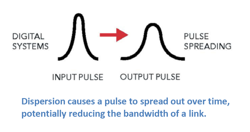
Dispersion
Most of the traffic traveling through fiber networks takes the form of a laser pulse, where the laser is pulsed on and off, effectively forming a digital square wave comprised of “1”s and “0”s. Dispersion causes a pulse to spread out over time, effectively rounding the edges, and making it harder for the detector to determine whether a “1” or a “0” is being transmitted. When this happens, the effective bandwidth of the link is reduced. The three main types of dispersion mechanisms are modal dispersion, chromatic dispersion, and polarization mode dispersion. Because these mechanisms affect fiber networks in different ways, we’ll discuss each in some depth. Please download the full article for more information.
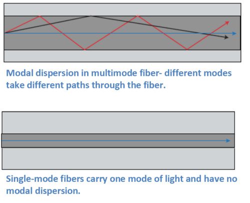
Modal Dispersion
In general, our article on Single-Mode Optical Fiber Selection focuses on single-mode fibers since they comprise the vast majority of fiber kilometers deployed around the world. In contrast to multimode fibers, single-mode fibers are used for all high-capacity, long-distance networks due to their low attenuation and high bandwidth. A main limiting factor of multimode fibers is modal dispersion.
Multimode fibers carry multiple modes of light at the same time. While a mode of light can be thought of as a ray of light, a typical multimode fiber can have up to 17 modes of light traveling along it at once. These modes all traverse slightly different paths through the fiber, with some path lengths longer than others. Modes that take a straighter path will arrive sooner, and modes that bounce along the outer edges of the core of the fiber take a longer path and arrive later. The effect on the end pulse is called modal dispersion, since it is due to the different modes in the fiber. Multimode fibers are designed to reduce the amount of modal dispersion with precise control of the index of refraction profile, through the quantity of dopants used in the core. However, it isn’t possible to completely eliminate modal dispersion in multimode fibers.
Chromatic Dispersion
Chromatic dispersion describes a combination
of two separate types of dispersion, namely material dispersion and waveguide
dispersion. Light travels at different speeds at different wavelengths, and all
laser pulses are transmitted over a wavelength range. Light also travels at
different speeds through different materials. These varying speeds cause pulses
to either spread out or compress as they travel down the fiber. Fiber designers
can use these two points to customize the index of refraction profile to
produce fibers for different applications. Chromatic dispersion isn’t always a
bad thing. In fact, it can be used as a tool to help optimize network
performance.
For example, the first lasers used for fiber
transmission operated at 1310 nm, and many networks still use that wavelength.
Fiber designers therefore developed the first single-mode fibers to have
minimum or zero dispersion at this wavelength. In fact, G.652 fibers are still
designed this way. In these fibers, dispersion is higher in the 1550 nm window.
Today’s networks often operate with multiple
wavelengths running over them. In these networks, nonlinear effects that result
from the multiple wavelengths can affect network operation. We’ll give a brief
overview of some of these non-linear effects in this article. Chromatic
dispersion is often used as a tool to help optimize these types of networks.
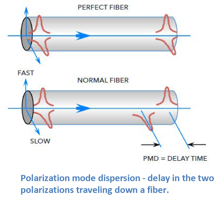
Polarization Mode Dispersion (PMD)
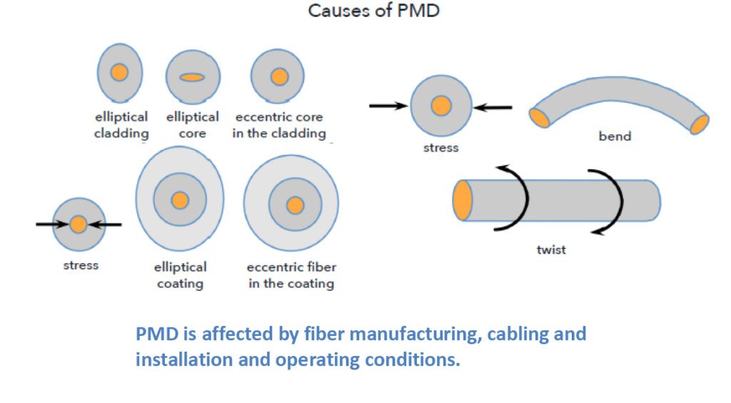
Light is an electromagnetic wave and is comprised of two polarizations that travel down the fiber at the same time. In a perfectly round fiber deployed with perfectly balanced external stresses, these polarizations would reach the end of the fiber at the same time. Of course, our world isn’t perfect. Even small amounts of glass ovality/non-concentricity or non-concentric stresses in the cable can cause one of the polarizations to travel faster than the other, spreading out in time as they travel along the fiber. This phenomenon is called polarization mode dispersion (PMD).
Cabling and installation affect PMD, and even
things like vibration from trains moving down tracks or wind-induced aerial
cable vibrations can affect PMD. However, the impacts of these interactions are
typically smaller than the inherent PMD caused by the glass manufacturing
process.
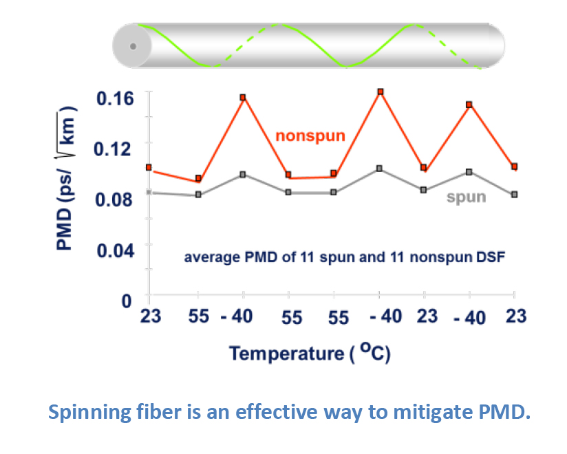
There are ways to mitigate PMD. One very
effective method is to make the glass fiber as geometrically round and
consistent as possible. OFS uses a special technique to accomplish this. Using
a patented process called fiber “spinning”; half-twists are translated through
the fiber during the draw process, reducing the non-concentricities and
ovalities in the glass that are the major contributors to increased PMD.
There are a host of other factors that
network, equipment, and fiber designers have needed to consider as network
capabilities have grown over the years. These factors often result as we
collectively add more and more wavelengths of traffic at greater speeds and
higher power levels.
It is not the intent of this article to review
each of these in depth, but instead to touch on them so the reader can have a
passing familiarity. The highest profile of these factors is four-wave mixing,
which led to the development of non-zero dispersion-shifted fibers (NZDF).
However, other non-linear effects include self-phase modulation, cross-phase
modulation, Raman and Brillouin scattering, and others. As mentioned earlier,
chromatic dispersion can be used to offset the effects of four-wave mixing. For
those non-linear effects related to higher power levels, increasing the
effective area where the light travels down the fiber can help to reduce the
impact of these other non-linear effects.
Dispersions and non-linear effects are the
least understood issues in the general fiber user population, mainly because
the guidelines used to match up today’s fibers and electronics typically work
so that the end user doesn’t need to have a detailed background to bring up a
system.
OFS has multiple decades of experience with fiber optic networks. Please contact your local OFS representative if you would like additional information regarding any of the items in this article.
OFS is a market leader in the design and manufacture of standard and custom Dispersion Slope Compensating Modules (DSCMs) also known as Dispersion Compensating Modules (DCMs). Our fixed broadband, reconfigurable, and tunable colorless modules round out a product line that is well-suited for the major transmission fiber types.
Optical fiber-to-the-business deployment is accelerating globally to support increasing internet speeds of up to 1 Gigabit per second, and 10 Gigabit speeds that are already available in some regions. Service providers are responding by installing optical fiber both to and deep inside buildings to the living unit.
The Solutions in this 64-page guide can help reduce both first and life cycle costs of optical fiber deployments to residential and business customers.
Solutions for both Greenfield installation during building construction and Brownfield installation in existing buildings are included. Scalable and optimized to fit a broad range of building structures, these solutions offer faster, reliable installation through innovative labor saving technologies, using less space than conventional approaches.
Solutions for both indoor and outdoor deployment offer flexibility to use the best available pathways for each building. The solution building blocks include a wide range of terminals, splitters, point-of-entry modules, riser cables, attic and wall fish fiber, hallway fiber and complete indoor living unit fiber kits. This portfolio allows service providers to select the best solution for each building, and OFS can help design building specific solutions and bills of material as a value added service.
OFS fiber-to-the-subscriber (FTTx) solutions help to revolutionize the speed of installing fibers; enhance the customer experience; minimize disruption; reduce labor costs; increase subscriber take rates; enable faster time to revenue for service providers; and get Gigabit and higher speeds faster to subscribers.
OPTICAL FIBER BUILDING CHALLENGES AND SOLUTIONS
Time to revenue: Fast and easy to install pre-terminated solutions can speed installation and reduce labor costs.
No pathways, requiring labor intensive cut and patch: Compact surface mounted fiber solutions.
Limited closet space: Smaller enclosures can enable installation of multiple operator connections in a small telecommunications closet.
Multiple boxes for splicing and splitter connections: Single box pre-terminated solutions can require less space and enable faster provisioning.
No duct space: Compact surface mounted fiber solutions either inside or on the outside of the building do not require duct.
Shared infrastructure: Compact cables can support multiple service providers in telecommunication pathways.
Fiber bends around many corners: Bend-insensitive fiber specified to support bend radius as low as 2.5 mm.
Disruptive/noisy to tenants: Optical solutions that are virtually invisible can be installed quickly and quietly and preserve the building decor.
Service disruptions and lost subscribers: Full solution of fiber, cable and connectors from one company, designed to work together. Factory tested to Tier 1 standards.
Multiple building types: Solutions to fit each building type.
PRE-TERMINATED vs. FIELD TERMINATED OPTICAL FIBER
Pre-terminated solutions are increasingly used to install fiber in Multiple Dwelling Unit (MDU) buildings to save time and money in higher labor cost regions. Pre-terminated products with built-in slack management are preferred so installers can neatly manage excess slack and use a single component to support multiple deployment lengths. Nevertheless, field terminated solutions can complement pre-terminated parts of the indoor or outdoor network and, for low labor cost markets, field terminated solutions may be preferred. OFS offers both pre-terminated and field terminated solutions to fit the needs of each service provider.
OPTICAL FIBER SPECIFICATIONS OPTIMIZED TO THE APPLICATION
Installing optical fiber in buildings and homes often requires conforming the fiber around sharp corners. EZ- Bend® Single-Mode Fiber offers outstanding bend performance down to a 2.5 mm radius for the most challenging in-residence and MDU applications. Compatible with the installed base of conventional G.652.D single-mode fibers, the fiber meets and exceeds ITU-T G.657.B3 recommendations. EZ-Bend fiber uses patented, groundbreaking EZ-Bend Optical Technology from OFS to provide three times lower loss at tight bends than competing G.657.B3 products.
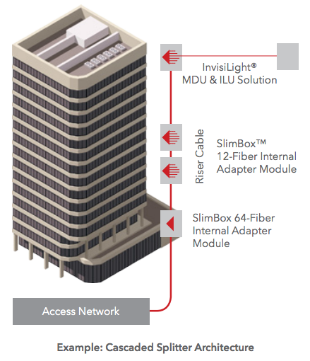
Centralized, Distributed and Distributed Cascaded Splitting
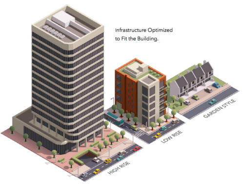
As FTTx deployment accelerates globally to meet increasing bandwidth needs, service providers must install optical fiber both to and inside the building for business and residential subscribers. Building types include duplexes, garden style, low rise (less than 10 floors), mid rise (10 to 15 floors), high rise (16 to 40 floors) and skyscrapers (40 floors and above). To provide building Gigabit services, providers must place optical cables in building risers and ducts, install optical fiber in hallways, and then take this fiber deep into the units, connecting to an indoor Optical Network Terminal (ONT). How can providers accomplish this in buildings that can vary widely in design, materials and available pathways?
Splitter Architectures
A typical PON network consists of the Optical Line Terminal (OLT) in a central office, head end or cabinet, connected by a feeder cable to optical splitters, and then to distribution cables downstream in the network. Choosing the right architecture depends upon end-user density, projected subscription rates and distance from the OLT. Splitter placement is important in FTTx design as it can significantly affect plant and electronics costs.
Three common types of splitter architectures are used when deploying FTTx:
Centralized splitting
Distributed splitting
Distributed cascaded splitting
To help meet these needs, the OFS portfolio supports all three splitter architectures, and features a broad range of solutions to meet the requirements of virtually any MDU deployment. For flexibility and regional preferences, these offers include a mix of pre-connectorized, in-field fusion splicing and mechanical connector solutions from which OFS can configure customized designs for each type of building.
Brownfield Outdoor Facade Solution
The Outdoor Facade Solution is used when property owners want to preserve the decor of the building exterior. The compact EZ-Bend Indoor/Outdoor cable is placed vertically on the exterior wall of the residence from an outdoor wall mount box to an indoor SlimBox® unit. The indoor SlimBox can be factory configured with SCA adapters or fanouts for a pre-terminated solution, or for fusion splicing. EZ-Bend jumpers are used for the path to each living unit. Pre-terminated EZ-Bend Jumpers are recommended for faster installation, or a mechanical connector may be used for field termination in the SlimBox Wall Plate. The 80×80 InvisiLight® Module can be used as a “fiber extension” to any location in the living unit. Alternatively, instead of EZ-Bend jumpers, the InvisiLight MDU solution may be placed in the hallway to the living units (not shown).
Brownfield Outdoor Facade Solution
Greenfield Pre-Terminated Solution
TELECOMMUNICATION ROOM
Compact basement box for a progressive customer activation;
The basement box (SlimBox 64F Terminal) allows fusion splices for the outside plant cable;
Ideal for buildings with low penetration rates: One splitter can be installed and the management of the customers is done through the SCA ports. A parking area permits easy connection of new customers;
Several boxes can be connected for modular expansion. Connections between multiple SlimBoxes are possible through access openings between them.
RISER BACKBONE
SCA pre-terminated cables for quick plug and play installation;
EZ-Bend patch cords directly from the apartment unit may be used for small buildings.
HORIZONTAL DEPLOYMENT
Direct deployment from the telecommunication closet to the apartment unit;
Ideal for Greenfield installation;
The EZ-Bend jumper is connected to an adapter installed in the SlimBox Wall Plate (inside the living unit).
INSIDE THE LIVING UNIT
An SCA mechanical connector can be used to terminate the EZ-Bend Jumper inside the living unit;
The InvisiLight ILU Solution is a complementary product used to extend the fiber inside the apartment.
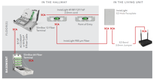
Greenfield Fusion Spliced or Field Terminated Solution
TELECOMMUNICATION ROOM
Compact basement box for a progressive customer activation (parking up to 48 connectors in the SlimBox 64F Terminal);
The basement box (SlimBox 64F Terminal) allows fusion splices for the outside plant cable and the internal cables (up to 96 fusion splices – 8 splice trays with 12 splices in each one);
Ideal for buildings with low penetration rate: One splitter can be installed with management of the customers done through the SCA ports. A parking area permits easy connection of new customers;
Several boxes can be connected for modular expansion. Connections between SlimBoxes are possible through access openings between them.
RISER BACKBONE
ACCUMAX® cables may be used for quick and easy installation:
SCA pre-terminated pigtails are used for fusion splicing inside the basement and floor boxes.
HORIZONTAL DEPLOYMENT
Direct deployment from the telecommunication closet to the apartment unit through EZ-Bend cable (ruggedized 3.0 or 4.8 mm);
The horizontal cable is fusion spliced or field terminated with a mechanical connector in the SlimBox 12F Terminal (floor distribution box) and in the SlimBox Wall Plate (inside the living unit).
INSIDE THE LIVING UNIT
An SCA mechanical connector can be used to terminate the EZ-Bend Jumper inside the living unit or a pre-terminated pigtail can be used;
The InvisiLight ILU Solution is a complementary product used to extend the fiber inside the apartment.
Compact basement box for progressive customer activation;
The basement box (SlimBox™ 64F Terminal) allows fusion splices to the outside plant cable;
Ideal for buildings with low penetration rate: One splitter can be installed with management of the customers done through the SCA ports. A parking area permits easy connection of new customers;
Boxes can be added for modular expansion. Connections between SlimBox units are easily made using jumpers through multiple ports designed into the box.
RISER BACKBONE
SCA pre-terminated cables for quick plug and play installation:
It is possible to place InvisiLight 2.0 mm 12-Fiber multifiber cord directly from the basement box and down hallways in small or garden style buildings.
HORIZONTAL DEPLOYMENT
The InvisiLight MDU Point of Entry (POE) Module offers a discrete solution using field termination inside the module;
Virtually invisible installation using the InvisiLight 12F Pre-terminated 2.0 mm cord.
INSIDE THE LIVING UNIT
InvisiLight ILU Solution is complementary and connects to the InvisiLight MDU installation;
InvisiLight ILU Solution is installed with the same tools and procedures as the InvisiLight MDU Solution
This 64-page guide with illustrations and part specifications will help in selecting the right fiber optic cables and accessories to reduce both the first and life cycle costs of fiber deployments to business customers inside buildings.
As transmission speeds over optical fiber networks in the enterprise increase to 10 Gigabits per second (Gb/s) and beyond, a relatively new term – “laser-optimized fiber” – has crept into the industry’s vocabulary. What is laser-optimized fiber? What do you need to know about it? And what exactly does the term “laser- optimized” mean? Understanding the answers to these questions will help you prepare for the latest wave in optical communications for enterprise networks.
Why have optical fibers been “optimized” for use with lasers?
Older “legacy” optical fiber systems (Token Ring, Ethernet, FDDI, ATM) used in premises applications operated at relatively slow speeds in the range of 4 to 155 Megabits per second (Mb/s). These systems utilized inexpensive light sources called Light Emitting Diodes (LEDs), which were perfectly adequate for these slower speeds. Multimode fibers used in these systems were rated to certain minimum bandwidths, typically:
160 MHz/km over 62.5/125 μm fiber at 850 nm
500 MHz/km over 50/125 μm fiber at 850 nm
500 MHz/km over both products at 1300 nm
These fibers were tested for bandwidth using an Overfilled Launch (OFL) test method, which accurately replicated real-life performance with an LED.
As the demand for bandwidth and higher throughput increased, especially in building and campus backbones, LEDs could not keep pace. With a maximum modulation rate of 622 Mb/s, LEDs would not support the 1 Gb/s and greater transmission rates required. One could make use of traditional lasers (Fabry-Perot, Distributed Feedback) typically used over single-mode fiber. However these are considerably more expensive due to the higher performance characteristics required for long-distance transmission on single-mode fiber.
In response, the industry developed a new high-speed laser light source called a Vertical Cavity Surface Emitting Laser (VCSEL). These VCSELs are inexpensive and well suited for low-cost 850 nm multimode transmission systems, allowing for data rates of 1 Gb/s and 10 Gb/s in the enterprise. With the emergence of these VCSELs, multimode fiber had to be “optimized” for operation with lasers.
VCSELs provide higher power, narrower spectral width, smaller spot size and faster data rates than LEDs. All of these advantages add up to a significant performance boost. This assumes, of course, the fiber itself does not hinder performance. To understand why this could occur, we need to recognize the differences between VCSELs and LEDs and how they transmit signals along a multimode fiber.
All LEDs produce a smooth, uniform output that consistently fills the entire fiber core and excites the many hundreds of modes in the fiber. The bandwidth of the fiber is determined by the aggregate performance of all the modes in the fiber. If a few modes lag behind or get ahead due to modal dispersion, they have little impact on bandwidth because many other modes are carrying the bulk of the signal.
The energy output of a VCSEL is smaller and more concentrated than that of an LED. As a result, VCSELs do not excite all the modes in a multimode fiber, but rather only a restricted set of modes. The bandwidth of the fiber is dictated by this restricted set of modes, and any modes that lag or get ahead have a much greater influence on bandwidth.
Typically, a VCSEL’s power would be concentrated in the center of the fiber, where older fibers were prone to defects or variations in the refractive index profile (the critical light-guiding property in the core of the fiber), resulting in poor transmission of the signal. That is why some fibers may actually perform poorly with a VCSEL compared to an LED.
To complicate matters, the power profile of a VCSEL is nonuniform and fluctuates constantly. It changes sharply across its face, varies from VCSEL to VCSEL and changes with temperature and vibrational fluctuations. Consequently, individual VCSELs will excite different modes in a certain fiber at any given time. And because different modes carry varying amounts of power, the fiber’s bandwidth can vary in an unpredictable manner.
Why are laser-optimized fibers the best choice for use with VCSELs?
With the advent of VCSELs, it became apparent that the traditional multimode fiber deployed for LED systems did not take full advantage of the performance benefits of VCSELs.
To fully capitalize on the benefits that VCSELs offered, fiber manufacturers developed laser-optimized multimode fiber (LOMMF). LOMMF is specifically designed, fabricated and tested for efficient and reliable use with VCSELs.
LOMMFs should have a well-designed and carefully controlled refractive index profile to ensure optimum light transmission with a VCSEL. Precise control of the refractive index profile minimizes modal dispersion, also known as Differential Mode Delay (DMD). This ensures that all modes, or light paths, in the fiber arrive at the receiver at about the same time, minimizing pulse spreading and, therefore, maximizing bandwidth. A good refractive index profile is best achieved through DMD testing.
VCSELs and LOMMF provide tremendous flexibility and cost efficiency in “freeing up” bandwidth bottlenecks in the enterprise today and well into the future. LOMMF is completely compatible with LEDs and other fiber optic applications (there are no special connectors or termination required and no effect on attenuation). LOMMF can be installed now and utilized at slower data rates until the need arises to increase network speed to 1 or even 10 Gb/s. At that point, you only need to upgrade the optics modules to VCSEL-based transceivers. There is no need to pull new cable.
Can you use any laser-optimized fiber for 10 Gb/s?
No — it is important to note that not all laser-optimized fiber is 10 Gb/s capable. If 10 Gb/s capacity is in your future, you must make sure that the LOMMF you’re installing now is capable of handling 10 Gb/s. The first laser-optimized fibers, introduced to the market in the mid-1990s, were designed for 1 Gb/s applications. Available in both 62.5/125 µm and 50/125 µm designs, these fibers extended the reach capability of 1 Gb/s systems beyond what the industry standards stated. For instance, OFS 1 Gb/s Laser Optimized 62.5 Fiber can go 300 meters in cost-effective, 1 Gb/s 850 nm (1000BASE-SX) systems. 50/125 µm fibers offer even greater performance, with a reach of 600 meters or more. These 1 Gb/s LOMMFs, coupled with 850 nm VCSELs, allow for the lowest systems cost for building backbones and short-to medium-length campus backbones
How do you measure bandwidth for laser-optimized fiber?
Since LEDs have a uniform and consistent power profile that excites all the modes in a multimode fiber, the traditional OFL method of bandwidth measurement accurately predicts bandwidth of fiber for LED applications. But because VCSELs only excite some of the modes in a fiber, and in a varying manner, the OFL bandwidth measurement cannot predict what the fiber’s bandwidth would be if the fiber were to be used in a VCSEL application.
It should become clear now why fiber manufacturers developed laser-optimized fiber, and why DMD testing is so important. The refractive index has to be well designed and controlled to ensure that all modes exhibit minimal DMD and all arrive at the other end of the fiber at the same time. No matter which modes in the fiber are actually guiding the light, those modes will have minimal DMD and provide high bandwidth.
What should you look for in DMD testing?
DMD testing provides a clear picture of how individual mode groups carry light down the fiber, and which mode groups are causing DMD. In fact, that picture is so clear that the standards require fiber to be DMD-tested to ensure adequate bandwidth to the rated distances for 10 Gb/s applications.
Tony Irujo is sales engineer for optical fiber at OFS, a world-leading designer, manufacturer and provider of optical fiber, fiber optic cable, connectivity, fiber-to-the-subscriber (FTTx)and specialty photonics products. Tony provides technical sales and marketing support for multimode and single-mode optical fiber.
Tony has 25 years of experience in optical fiber manufacturing, testing and applications. He started with SpecTran in 1993 as a quality and process engineer and transitioned to more customer-focused roles with Lucent and OFS. He represents OFS in the Fiber Optic LAN Section (FOLS) of the TIA, has authored several papers on fiber technology and applications and is a frequent speaker at industry events. Tony has a Bachelor of Science degree in Mechanical Engineering from Western New England College in Springfield, MA.
Learn the differences and when to use single-mode vs multimode fiber.
Cloud computing and web services continue to drive increased bandwidth demand, pushing data communications rates from 1 and 10G to 40 and 100G and beyond in enterprise and data center networks.
These higher speeds might lead system designers to believe that single-mode optical fiber enjoys an increasing advantage over multimode optical fiber in premises applications. However, higher Ethernet speeds do not automatically mean that single-mode optical fiber is the right choice.
Although single-mode optical fiber holds advantages in terms of bandwidth and reach for longer distances, multimode optical fiber easily supports most distances required for enterprise and data center networks, at a cost significantly less than single-mode.
Total Cost Comparison of Single Mode vs Multimode Fibers
Multimode optical fiber continues to be the more cost-effective choice over single-mode optical fiber for shorter-reach applications. While the actual cost of multimode cable is greater than that of single-mode fiber optic cable, it is the optics that dominate the total cost of a network system, dwarfing variation in cable costs.
On average, single-mode transceivers continue to cost from 1.5 to 4 – 5 times more than multimode transceivers, depending on the data rate. As faster optoelectronic technology matures and volumes increase, prices come down for both, and the cost gap between multimode and single-mode decreases. However, single-mode optics have always been more expensive than their equivalent multimode counterparts. This fact is supported by the difference in multimode vs. single-mode 10G optics, a common Ethernet speed used today.
Multimode transceivers also consume less power than single-mode transceivers, an important consideration especially when assessing the cost of powering and cooling a data center. In a large data center with thousands of links, a multimode solution can provide substantial cost savings, from both a transceiver and power/cooling perspective.
Finally, the fact that multimode optical fiber is easier to install and terminate in the field is an important consideration for enterprise environments, with their frequent moves, adds and changes.
The Difference Between Multimode and Single-Mode Fibers
The way in which these two fiber types transmit light eventually led to their separate names. Generally designed for systems of moderate to long distance (e.g., metro, access and long-haul networks), single-mode optical fibers have a small core size (< 10 µm) that permits only one mode or ray of light to be transmitted. This tiny core requires precision alignment to inject light from the transceiver into the core, significantly driving up transceiver costs.
In comparison, multimode optical fibers have larger cores that guide many modes simultaneously. The larger core makes it much easier to capture light from a transceiver, allowing source costs to be controlled. Similarly, multimode connectors cost less than single-mode connectors as a result of the more stringent alignment requirements of single-mode optical fiber. Single-mode connections require greater care and skill to terminate, which is why components are often pre-terminated at the factory. On the other hand, multimode connections can be easily performed in the field, offering installation flexibility, cost savings and peace of mind.
For these reasons, multimode optical fiber systems continue to be the most cost-effective fiber choice for enterprise and data center applications up to the 500 – 600 meter range.
Beyond the reach of multimode optical fibers, it becomes necessary to use single-mode optical fiber. However, when assessing single-mode optical fibers, be sure to consider newer options. A bend-insensitive, full-spectrum single-mode optical fiber provides more transceiver options, greater bandwidth and is less sensitive to handling of the cables and patch cords than is conventional single-mode optical fiber.
At one time, the network designer or end user who specified multimode optical fiber for short reach systems had to choose from two fiber types defined by their core size, namely, 50 micron (µm) or 62.5 µm. Now, that choice is slightly different: choose from OM3, OM4, or the new OM5 grade of 50 µm multimode optical fibers. Today, 62.5 µm OM1 multimode optical fiber is virtually obsolete and is relegated for use with extensions or repairs of legacy, low bandwidth systems. In fact, 62.5 µm OM1 fiber supports only 33 meters at 10G and is not even recognized as an option for faster speeds.
50 µm multimode optical fibers were first deployed in the 1970s for both short and long reach applications. But as data rates increased, 50 µm fiber’s reach became limited with the LED light sources used at the time. To resolve this, 62.5 µm multimode optical fiber was developed and introduced in the 1980s. With its larger core, 62.5 µm optical fiber coupled more signal power than 50 µm optical fiber, allowing for longer reach (2 kms) at 10 Mb/s to support campus applications. That was the only time when 62.5 µm fiber offered an advantage over 50 µm optical fiber.
With the advent of gigabit (1 Gb/s) speeds and the introduction of the 850 nm VCSEL laser light source in the mid-1990s, we saw a shift back to 50 µm optical fiber, with its inherently higher bandwidth. Today, 50 µm laser-optimized multimode (OM3, OM4, and OM5) optical fibers offer significant bandwidth and reach advantages for short reach applications, while preserving the low system cost advantages of multimode optical fiber.
Planning for the Future
Industry standards groups including IEEE (Ethernet), INCITS (Fibre Channel), TIA, ISO/IEC and others continue to include multimode optical fiber as the short reach solution for next generation speeds. This designation reinforces multimode optical fiber’s continued economic advantage for these applications.
IEEE includes multimode optical fiber in its 40G and 100G Ethernet standards as well as its pending 50G, 200G, and 400G standards. In addition, TIA issued a new standard for the next generation of multimode optical fiber called wide band (OM5) multimode optical fiber. This new version of 50 µm optical fiber can transmit multiple wavelengths using Short Wavelength Division Multiplexing (SWDM) technology, while maintaining OM4 backward compatibility. In this way, end users can obtain greater bandwidth and higher speeds from a single fiber by simply adding wavelengths. The OFS version of this fiber is called LaserWave® WideBand Optical Fiber. This new fiber allows for continued economic benefit in deploying short reach optics using multimode optical fiber – as opposed to more expensive single-mode optics.
In Conclusion
In general, multimode optical fiber continues to be the most cost-effective choice for enterprise and data center applications up to the 500 – 600 meter range. Beyond that, single-mode optical fiber is necessary.
>> Download the Full Article to Learn More about the Difference between Multimode or Single-Mode Optical Fibers
Download the OFS single-mode optical fiber selection guide for terrestrial applications. Optical fiber applications include transcontinental, regional, metropolitan, home/business access and in-building fiber optic systems. The guide describes several families of OFS optical fibers and provides recommendations for single-mode fibers used in Outside Plant (OSP) as well as Indoor (Premises, Enterprise) applications and their benefits.
Selecting the right single-mode fiber for your application can help lower system costs. Characteristics such as lower loss, larger effective area, optimized dispersion and tight bend performance can provide economic benefits compared to using a standard G.652.D single-mode fiber. Please contact OFS for more thorough explanations of the various fiber value propositions to assist with the selection process.
OFS families of Single-Mode Optical Fibers include:
• TeraWave® Optical Fibers - ITU-T G.654 long haul fiber with optimized large effective area designed specifically to support coherent systems.
• TrueWave® Optical Fibers – ITU-T G.655 and/or G.656 Non-Zero Dispersion fibers (NZDF) that have reduced chromatic dispersion characteristics to simplify dispersion compensation.
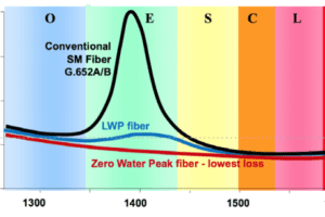
• AllWave® Optical Fibers – ITU-T G.652.D standard single-mode fibers. AllWave Fibers provide seamless splicing and are zero water peak (ZWP) and can be used everywhere from long haul to shorter reach in-building applications. Some of these fibers are also G.657 compliant.
• AllWave® FLEX and EZ-Bend® Optical Fibers are ITU-T G.657 bend insensitive single-mode fibers
Single-Mode Optical Fiber Application Comparison Charts Include:
• Long Haul - >1000 km*
• Regional, Metro, Utility, Wireless Backhaul - 60 to 1000 km
• FTTx: Home, Business, Cell Site - Up to 60 km - All types and data rates of PON and single-mode point-to-point networks.
• High Density Applications
Premises, Drop, Cabinet and Connectivity Application Selection Charts Include:
• Central Office, Head End, Data Center, Cabinets, Fiber to the Antenna, General In-Building
• Drop and in the Living Unit
A huge increase in digital devices, cloud computing and web services have helped fuel the tremendous demand for increased bandwidth while also pushing datacom rates to 100G and beyond. With these faster speeds and greater use, system designers might assume that single-mode optical fiber holds a growing advantage over multimode optical fiber for premises applications. However, it’s critical to remember that increased Ethernet speeds don’t necessarily mean that single-mode fiber is the best choice.
While it’s true that single-mode fiber holds bandwidth and reach advantages, especially for longer distances, multimode fiber easily supports most distances needed by data center and enterprise networks, and at a significant cost savings over single-mode fiber.
What’s the Difference?
These two optical fiber types were primarily named for the different ways that they transmit light. Single-Mode optical fibers have a small core size (less than 10 microns) and allow only one mode or ray of light to be transmitted. These fibers were mainly designed for networks that involve medium to long distances, such as metro, access and long-haul networks.
On the other hand, multimode fibers have larger cores that work to guide many modes at the same time. These larger cores make it much easier to capture light from a transceiver, helping to control source costs.
Today, network designers and end users can choose from OM3, OM4 or OM5 grades of 50 micron multimode fibers. At one time in the 1980s, as data rates increased, 62.5 micron fiber was introduced because it allowed for longer reach to support campus applications. However, with the advent of gigabit speeds, users moved back to 50 micron fiber with its inherently higher bandwidth. Now 50 micron laser-optimized multimode OM3, OM4 and OM5 fibers offer major bandwidth and reach advantages for short-reach applications along with low system costs.
The Future
Industry standards groups such as IEEE (Ethernet), TIA, ISO/IEC and others continue to recognize multimode optical fiber as the short-reach solution for next-generation speeds. In fact, TIA issued a new standard for the next generation of multimode fiber called wide band (OM5) multimode fiber. This new version of 50 micron fiber can transmit multiple wavelengths using Short Wavelength Division Multiplexing (SWDM) technology, while maintaining OM4 backward compatibility. This capability lets end users gain greater bandwidth and higher speeds from a single fiber by simply adding wavelengths. The OFS version of this fiber is LaserWave® WideBand (OM5) Optical Fiber.
In Short…
Generally, 50 micron optical fiber continues to be the most cost-effective choice for enterprise and data center use up to the 500-600 meter range. Beyond that distance, single-mode optical fiber is necessary.
The OFS LaserWave FLEX Multimode Optical Fiber family offers full performance range and has better optical and geometric specifications than standards require. However, if the network’s transmission distance requires the use of single-mode optical fiber, consider bend-insensitive, zero water peak (ZWP) full-spectrum fibers such as the OFS family of AllWave® Optical Fibers.


 A typical PON network consists of the Optical Line Terminal (OLT) in a central office, head end or
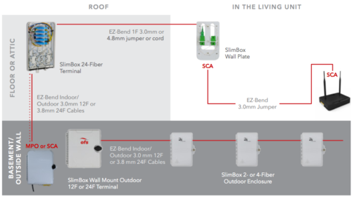
 No — it is important to note that not all laser-optimized fiber is 10 Gb/s capable. If 10 Gb/s capacity is in your future, you must make sure that the LOMMF you’re installing now is capable of handling 10 Gb/s. The first laser-optimized fibers, introduced to the market in the mid-1990s, were designed for 1 Gb/s applications. Available in both 62.5/125 µm and 50/125 µm designs, these fibers extended the reach capability of 1 Gb/s systems beyond what the industry standards stated. For instance, OFS 1 Gb/s
 Multimode transceivers also consume less power than single-mode transceivers, an important consideration especially when assessing the cost of powering and cooling a data center. In a large data center with thousands of links, a multimode solution can provide substantial cost savings, from both a transceiver and power/cooling perspective.
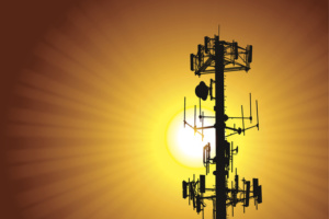 Beyond the reach of multimode optical fibers, it becomes necessary to use single-mode optical fiber. However, when assessing single-mode optical fibers, be sure to consider newer options. A bend-insensitive, full-spectrum single-mode optical fiber provides more transceiver options, greater bandwidth and is less sensitive to handling of the cables and patch cords than is conventional single-mode optical fiber.
 Industry standards groups including IEEE (Ethernet), INCITS (Fibre Channel), TIA, ISO/IEC and others continue to include multimode optical fiber as the short reach solution for next generation speeds. This designation reinforces multimode optical fiber’s continued economic advantage for these applications.