
for 50 and 62.5 µm GiHCS®, 200 µm HCS® LC Connectors
Important Safety and Warranty Information
Please Read First!
Please make sure to READ and understand the termination instructions completely. Improper assembly will cause poor termination results and cause damage to termination kit components.
Download the pdf document for the full instructions
Make sure you WEAR eye protection during the termination process. Bare optical fiber is sharp and may splinter; handle very carefully and make use of the provided fiber optic shard disposal container.
For more information please CONTACT the sales representative in your region or call the factory for technical support:
Mon-Friday, 8:00 am-5:00 pm EST.
860-678-6636
770-798-5555 [Outside the USA and Canada]
Content
LC Termination Kit Contents
Related Products and Accessories (Sold Separately)
LC and LC Duplex Connectors
Insertion Loss Test Kit
Termination Instructions
Step 1: Slide Strain Relief Boot
Step 2: Remove Outer Cable Jacket
Step 3: Remove ETFE Buffer
Step 4: Install Connector Body
Step 5: Cleave Optical Fiber
Step 6: Install Anti-snag Latch or Duplexing Clip
Maintenance & Trouble Shooting Guide
Importance of Cleave Tool Cleaning
Cleave Tool Cleaning Kit
Troubleshooting
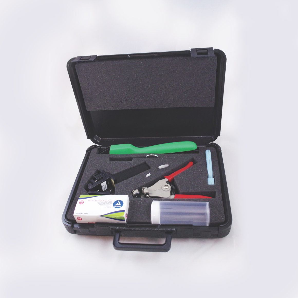
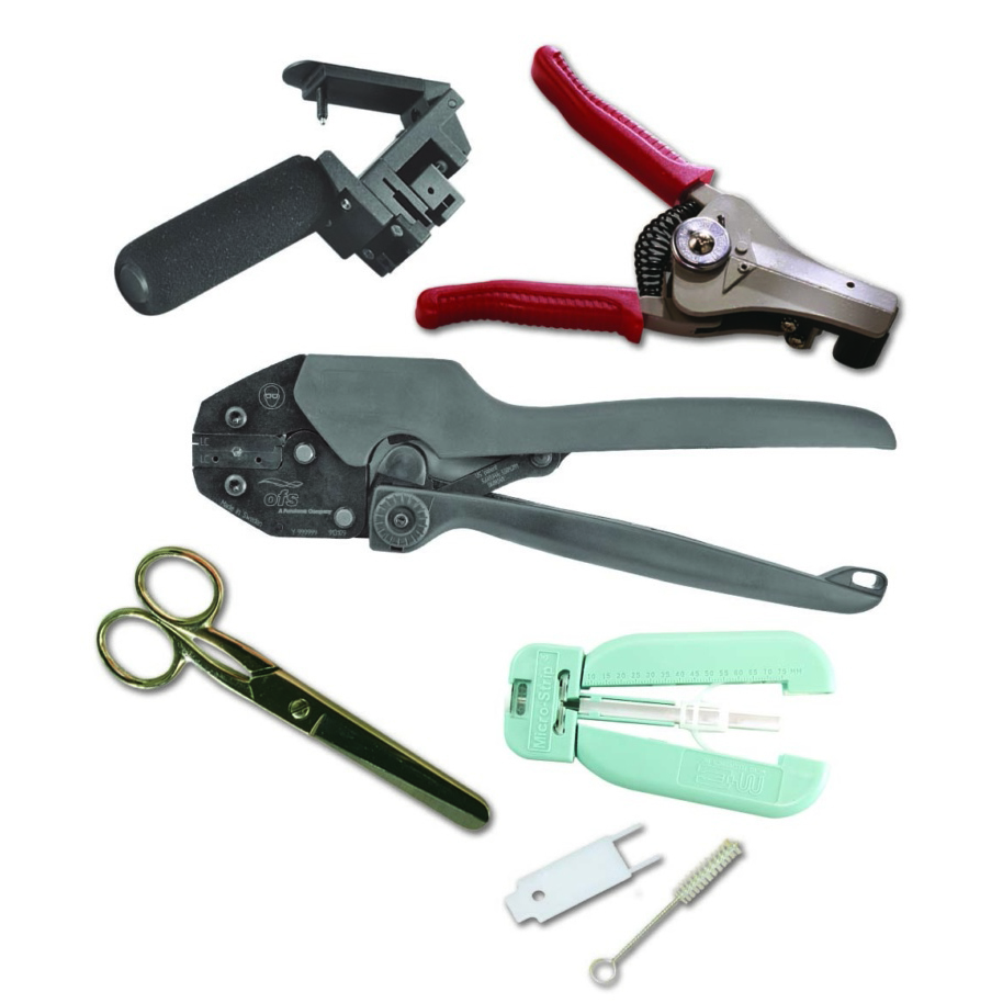
LC Termination Kit Contents
Kit Contents
Part Numbers/Description
DT03732-LC1 . . . . . . . . . . . GiHCS LC Termination Kit
DT03732-LC2 . . . . . . . . . . GiHCS LC Cleave Tool Only
P76859 . . . . . . . . . . . . . . GiHCS LC Instruction Manual
AP01224 . . . . . . . . . . . . . . . . . . . . . . . Cable Strip Tool
BT03865-07 . . . . . . . . . Crimp Tool LC (Black Handles)
CP01229-22 . . . . . . . . . ETFE Buffer Stripper w/ prong tool and brush
AP01225 . . . . . . . . . . . . . . . . . . . . . . . . . . . . . . Scissors
K60791 . . . . . . . . . . . Optical Fiber Shard Disposal Unit
K60792 . . . . . . . . . . . . . Alcohol Prep Pad (Box of 100)
Other Items Required (not included in kit): Safety Glasses, Marker
Order an OFS LC Termination Kit Number DT03732-LC1 Now
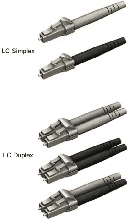
Related Products and Accessories (Sold Separately)
Part Numbers/Description
P26763-01 . . . . . . . . LC Simplex Connector (Beige Boot)
P26763-02 . . . . . . . . . LC Simplex Connector (Black Boot)
P26764-01 . . . . . . . LC Duplex Connector (2 Beige Boots)
P26764-02 . . . . . . . LC Duplex Connector (2 Black Boots)
P26764-03 . . . . . . . . . . . . LC Duplex Connector (1 Beige + 1 Black Boots)
P10188-15 . . . . . . . . . . . . . . . . . . Insertion Loss Test Kit for 50 and 62.5 µm GiHCS LC Connectors
P16247 . . . . . . . . . . . . . . . . . . . . Cleave Tool Cleaning Kit (Includes cleaning fluid and safe cleaning swabs)
STEP 1: Install Strain Relief Boot
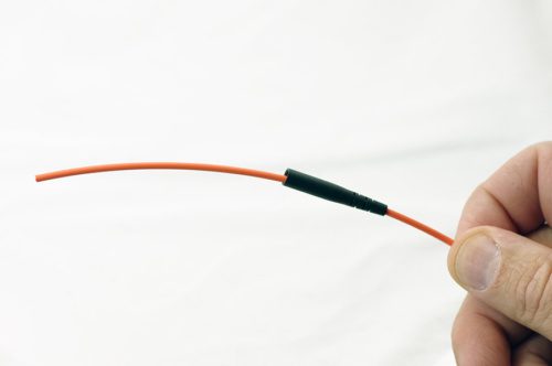
Slide STRAIN RELIEF BOOT (tapered end first) onto cable end and slide approximately 3 inches [76 mm] out of way.
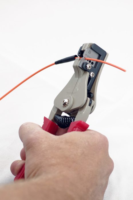
STEP 2: Remove Outer Cable Jacket
- Mark cable outer jacket 2.5 inches [63.5 mm] from cable end with a marker
- Using 2nd hole (marked 1.6) from the open side of the cable jacket strip tool, remove the 2.5 inches [63.5 mm] of outer jacket.
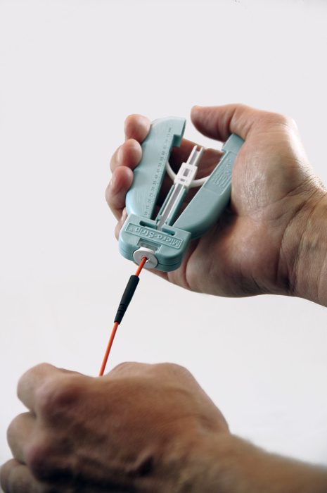
STEP 3: Remove ETFE Buffer
- Insert the buffered fiber through the guide tube of the ETFE Buffer Strip Tool, all the way in until the cable jacket bottoms out inside it.
- Holding cable securely, squeeze the tool’s handles to cut ETFE buffer then PULL STRAIGHT to remove the ETFE buffer.
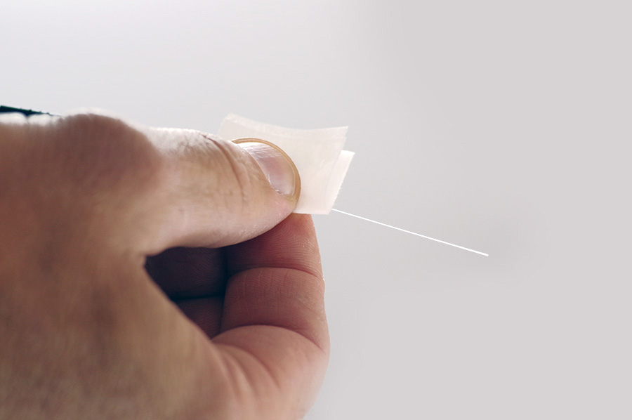
- With alcohol prep pad folded in two, wipe the surface of fiber where the ETFE buffer was just removed.
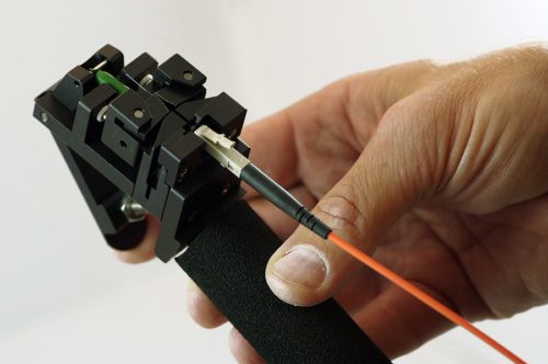
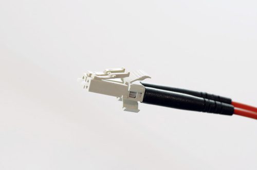
STEP 4: Install Connector Body
- Locate the CONNECTOR BODY subassembly into the CRIMP TOOL nest as shown. Close the crimp tool handles lightly to secure connector in nest, but do not yet apply crimp
- Insert stripped fiber into CONNECTOR BODY subassembly until the cable jacket bottoms out inside the connector
- Squeeze handles of CRIMP TOOL to apply crimp. CRIMP TOOL will not release until fully crimped.
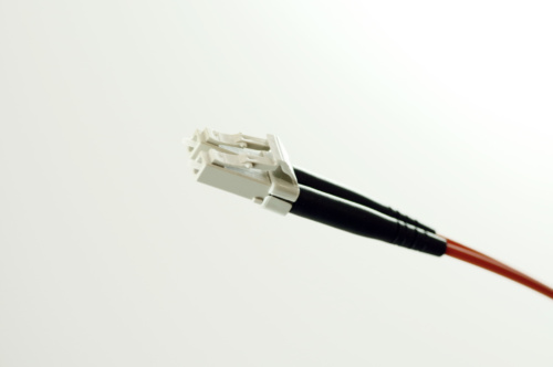
- Remove CONNECTOR from CRIMP TOOL nest. Slide up and
- install BOOT onto CONNECTOR.
- Locate the CONNECTOR BODY subassembly into the CRIMP TOOL nest as shown. Close the crimp tool handles lightly to secure connector in nest, but do not yet apply crimp
- Insert stripped fiber into CONNECTOR BODY subassembly until the cable jacket bottoms out inside the connector
- Squeeze handles of CRIMP TOOL to apply crimp. CRIMP TOOL will not release until fully crimped.
- Remove CONNECTOR from CRIMP TOOL nest. Slide up and
- install BOOT onto CONNECTOR.
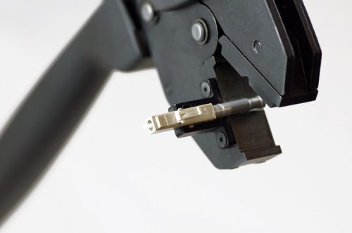
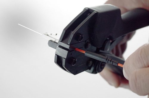
STEP 5: Cleave Optical Fiber
- Holding the CLEAVE TOOL in a horizontal position, grip the handle while leaving your index finger free to actuate trigger
- Gently insert CONNECTOR BODY into cleave tool as shown. Be sure to have it fully inserted and release the CONNECTOR BODY
- Using index finger, slowly depress trigger to perform the cleave operation. The cleave process is complete when the optical fiber snaps away
- from the connector. Do not release the trigger just yet!
- Before releasing the trigger, remove CONNECTOR BODY from the
- cleave tool and grasp the optical fiber scrap while releasing the trigger.
- Gently remove the scrap fiber from the cleave tool while keeping it away from the tool’s diamond blade. Place the scrap optical fiber into the fiber optic shard container for safe disposal.
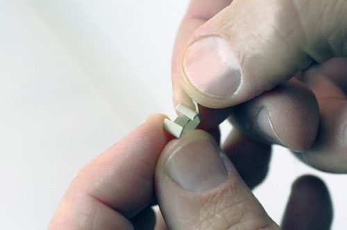
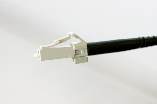
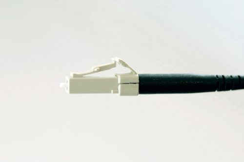
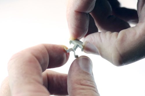
STEP 6: Install Anti-snag Latch or Duplexing Clip
Simplex Connector:
• Spread the clip slightly as shown.
• Install the clip around the connector, aligning as shown.
• Wrap around and snap on to secure.
Duplex Connector:
• Spread the clip slightly as shown.
• Install the clip around the connectors, aligning as shown.
• Wrap around and snap on to secure.
The PDF document also includes a Cleave Tool Cleaning Guide:
For cleaning your cleave tool, please order the OFS Cleave
Tool Cleaning Kit (part #P16247) which includes recommended cleaning fluid, swabs, and complete instructions.
The PDF document also includes a fiber optic troubleshooting guide for:
- Dim-light termination and no light termination
- Poor cleave quality or high insertion loss
- If the fiber does not cleave
- If the fiber protrudes or recesses after cleave
Download our LC Connector Family Spec Sheet
Visit our Knowledgebase and filter by Installation Resource to find a list of all our fiber optic instructions.
Learn more about our fiber optic building solutions
Tags: connectors, crimp and cleave, HCS fiber