We use cookies to help us provide you with a more enhanced and personalized experience adapted to your interests. By using our site you agree to our Terms of Use and Privacy Policy, including our use of cookies.
What is IEEE Std 802.3cm-2020, 400 Gb/s over Multimode Fiber?
The work of the IEEE Std P802.3cm Task Force was approved as a new standard by the IEEE-SA Standards Board on 30 January 2020, creating the latest 400 Gb/s Ethernet standard using multimode fiber. 400 Gb/s is the highest Ethernet speed, and 400 Gb/s optical modules are needed in hyperscale (Google, Microsoft, Alibaba, and others) and very large-scale enterprise datacenters. 802.3cm defines 400 Gb/s solutions over both 4-pair (400GBASE-SR4.2) and 8-pair (400GBASE-SR8) multimode links. The IEEE P802.3cm Task Force was chaired by Robert Lingle, Jr., Senior Director of Market Strategy at OFS.
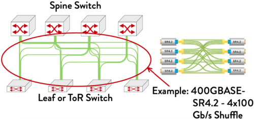
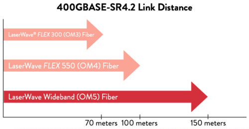
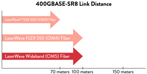
400GBASE-SR4.2 is the first multimode standard to use two wavelengths (850nm and 910nm), enabling 100 Gb/s transmission over a single fiber pair. It takes advantage of the multi-wavelength capabilities of OFS LaserWave® WideBand (OM5) fiber with 150 meter link distances, while supporting 100 meter links over LaserWave FLEX 550 (OM4) fiber and 70 meter links over LaserWave FLEX 300 (OM3) fiber. This builds on well-established 40 and 100G BiDi and SWDM technology that has been offered by switch and transceiver suppliers over the past decade. A key motivation for the 400GBASE-SR4.2 transceiver type is support of the installed base of multimode fiber cabling, designed around 100 meter reach over OM4 MMF, as well as extended reach over OM5 MMF, especially in large enterprise datacenters. 400GBASE-SR8 uses eight pairs of multimode fiber, with each pair supporting 50 Gb/s transmission. It operates over a single wavelength (850nm). OM4 and OM5 will support 100 meter links, while OM3 can support up to 70 meters. A key motivation for 400GBASE-SR8 is support of new cabling architectures in hyperscale datacenters.
What applications will use these links?
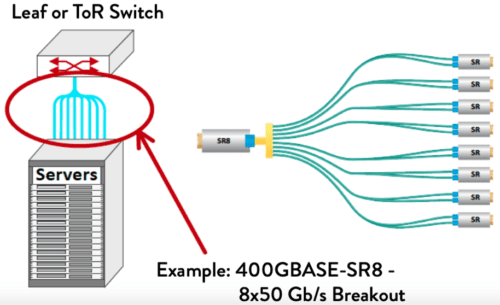
400 Gb/s multimode links can be used in a variety of applications. These include not only 400 Gb/s switch-to-switch (point-to-point) links, but several new applications, including 400GBASE-SR8 – 8x50GBASE-SR breakouts, or 400 Gb/s shuffles (fig. 1). The breakout application minimizes the number of ports on the Top-of-Rack (ToR) switch, providing connectivity to higher numbers of servers from a single switch. In similar fashion, the shuffle application allows a single 400 Gb/s switch port to support 100 Gb/s links to 4 different switches. 400GBASE-SR8 supports both flexibility and higher density: a 400G-SR8 OSFP/ QSFP DD transceiver can be used as 400GBASESR8, 2x200GBASE-SR4, 4x100GBASE-SR2, or 8x50GBASE-SR. 400GBASE-SR8 is already being deployed as 2x200GBASE-SR4. 5 THINGS YOU SHOULD KNOW ABOUT A Furukawa Company IEEE Std 802.3cm™-2020 For more information, visit our website at www.ofsoptics.com 1 2 Example: 400GBASE-SR8 – 8×50 Gb/s Breakout.
Shuffle Arrangement
Breakout Arrangement
What
does this mean for hyperscale data centers?
Both 400GBASE-SR4.2 and 400GBASE-SR8 applications can be used for point to point 400 Gb/s links between switches. Additionally, new applications are being deployed in hyperscale data centers. As server speeds reach 50 and 100 Gb/s, racks will contain fewer servers, leading to a change in switch architecture away from ToR to Middle-of-Row (MoR) or End-of-Row (EoR) switches. Copper DAC links are reaching link distance and bandwidth limitations that will make it very difficult to support this change in architecture, leading to demand for a low cost, short reach optical solution. 400GBASE-SR8 provides support for eight 50 Gb/s server links from a single MoR or EoR switch port, significantly increasing bandwidth density on the switch faceplate.
What does IEEE Std 802.3cm mean for enterprise data centers?
400GBASE-SR4.2 is the first 400 Gb/s
standard that takes advantage of the 4-pair OM3/OM4/OM5 infrastructure many
enterprises installed earlier, first for 40 Gb/s Ethernet and later, 100 Gb/s
100GBASESR4, and 200 Gb/s 200G-SR4. It provides a graceful evolution path for
enterprise networks, using the same cable infrastructure through at least four
Ethernet generations. Future advances point toward the ability to support even
higher data rates as they become needed. It takes advantage of the latest
multimode fiber technology, OM5 fiber, using multiple wavelengths to transmit
100 Gb/s over a pair of fibers over 150 meters, compared to 100 meters for OM4
and 70 meters over OM3.
400GBASE-SR8 will be used in enterprise data centers as 50 Gb/s servers are deployed. Most enterprise datacenter servers operate at lower data rates, however with 10 Gb/s server links being quite common.
What is coming next?
IEEE has already created a study group to investigate the development of 100 Gb/s per wavelength multimode solutions, known as the “100 Gb/s Wavelength Short Reach PHYs Study Group.” This will enable support of next generation 100 Gb/s server ports, expected in 2021-2022. By providing native 100 Gb/s support, no expensive “gearboxes” will be required to combine 50 Gb/s lanes, providing a low cost, power efficient optical solution. Beyond 2021-2022 timeframe, once an 800 Gb/s Ethernet MAC is standardized, using this technology with two-wavelength operation could create an 800 Gb/s, four-pair link, while a single wavelength could support an 800 Gb/s eight-pair link.
This article focuses on the parameters that affect available bandwidth in optical fibers, and the dispersion mechanisms of various fiber types and non-linear effects. Dispersion describes the process of how an input signal broadens out as it travels down the fiber. There are several types of dispersions that we will cover. We’ll also take a cursory look at other important nonlinear effects that can reduce the amount of bandwidth that is ultimately available over an optical fiber.
Dispersion
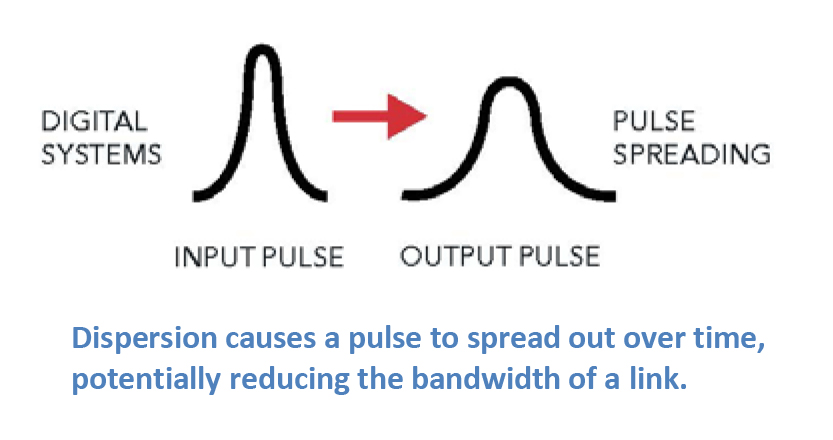
Most of the traffic traveling through fiber networks takes the form of a laser pulse, where the laser is pulsed on and off, effectively forming a digital square wave comprised of “1”s and “0”s. Dispersion causes a pulse to spread out over time, effectively rounding the edges, and making it harder for the detector to determine whether a “1” or a “0” is being transmitted. When this happens, the effective bandwidth of the link is reduced. The three main types of dispersion mechanisms are modal dispersion, chromatic dispersion, and polarization mode dispersion. Because these mechanisms affect fiber networks in different ways, we’ll discuss each in some depth. Please download the full article for more information.
Modal Dispersion
In general, our article on Single-Mode Optical Fiber Selection focuses on single-mode fibers since they comprise the vast majority of fiber kilometers deployed around the world. In contrast to multimode fibers, single-mode fibers are used for all high-capacity, long-distance networks due to their low attenuation and high bandwidth. A main limiting factor of multimode fibers is modal dispersion.
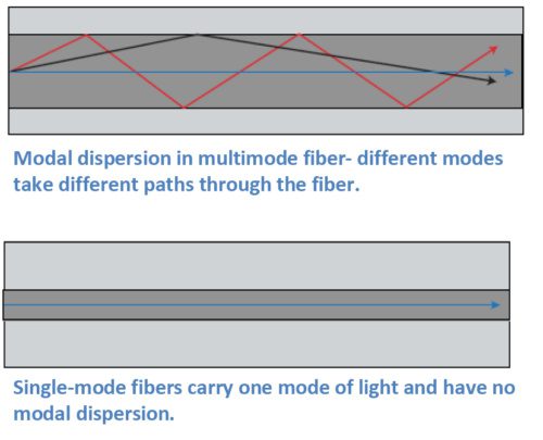
Multimode fibers carry multiple modes of light at the same time. While a mode of light can be thought of as a ray of light, a typical multimode fiber can have up to 17 modes of light traveling along it at once. These modes all traverse slightly different paths through the fiber, with some path lengths longer than others. Modes that take a straighter path will arrive sooner, and modes that bounce along the outer edges of the core of the fiber take a longer path and arrive later. The effect on the end pulse is called modal dispersion, since it is due to the different modes in the fiber. Multimode fibers are designed to reduce the amount of modal dispersion with precise control of the index of refraction profile, through the quantity of dopants used in the core. However, it isn’t possible to completely eliminate modal dispersion in multimode fibers.
Chromatic Dispersion
Chromatic dispersion describes a combination
of two separate types of dispersion, namely material dispersion and waveguide
dispersion. Light travels at different speeds at different wavelengths, and all
laser pulses are transmitted over a wavelength range. Light also travels at
different speeds through different materials. These varying speeds cause pulses
to either spread out or compress as they travel down the fiber. Fiber designers
can use these two points to customize the index of refraction profile to
produce fibers for different applications. Chromatic dispersion isn’t always a
bad thing. In fact, it can be used as a tool to help optimize network
performance.
For example, the first lasers used for fiber
transmission operated at 1310 nm, and many networks still use that wavelength.
Fiber designers therefore developed the first single-mode fibers to have
minimum or zero dispersion at this wavelength. In fact, G.652 fibers are still
designed this way. In these fibers, dispersion is higher in the 1550 nm window.
Today’s networks often operate with multiple
wavelengths running over them. In these networks, nonlinear effects that result
from the multiple wavelengths can affect network operation. We’ll give a brief
overview of some of these non-linear effects in this article. Chromatic
dispersion is often used as a tool to help optimize these types of networks.
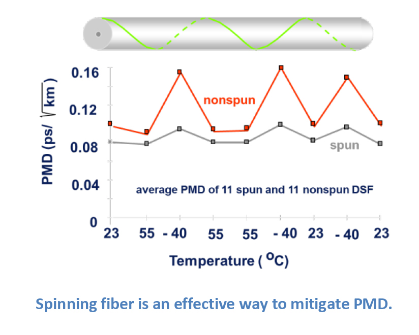
Polarization Mode Dispersion (PMD)
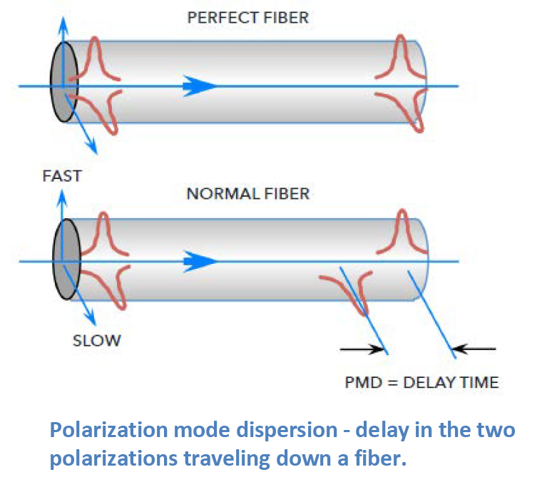
Light is an electromagnetic wave and is comprised of two polarizations that travel down the fiber at the same time. In a perfectly round fiber deployed with perfectly balanced external stresses, these polarizations would reach the end of the fiber at the same time. Of course, our world isn’t perfect. Even small amounts of glass ovality/non-concentricity or non-concentric stresses in the cable can cause one of the polarizations to travel faster than the other, spreading out in time as they travel along the fiber. This phenomenon is called polarization mode dispersion (PMD).
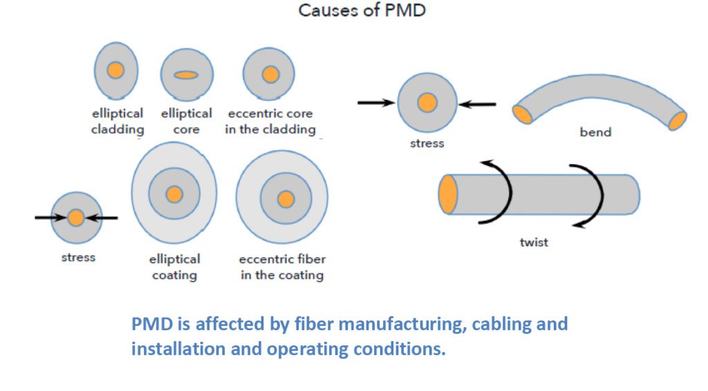
Cabling and installation affect PMD, and even
things like vibration from trains moving down tracks or wind-induced aerial
cable vibrations can affect PMD. However, the impacts of these interactions are
typically smaller than the inherent PMD caused by the glass manufacturing
process.
There are ways to mitigate PMD. One very
effective method is to make the glass fiber as geometrically round and
consistent as possible. OFS uses a special technique to accomplish this. Using
a patented process called fiber “spinning”; half-twists are translated through
the fiber during the draw process, reducing the non-concentricities and
ovalities in the glass that are the major contributors to increased PMD.
There are a host of other factors that
network, equipment, and fiber designers have needed to consider as network
capabilities have grown over the years. These factors often result as we
collectively add more and more wavelengths of traffic at greater speeds and
higher power levels.
It is not the intent of this article to review
each of these in depth, but instead to touch on them so the reader can have a
passing familiarity. The highest profile of these factors is four-wave mixing,
which led to the development of non-zero dispersion-shifted fibers (NZDF).
However, other non-linear effects include self-phase modulation, cross-phase
modulation, Raman and Brillouin scattering, and others. As mentioned earlier,
chromatic dispersion can be used to offset the effects of four-wave mixing. For
those non-linear effects related to higher power levels, increasing the
effective area where the light travels down the fiber can help to reduce the
impact of these other non-linear effects.
Dispersions and non-linear effects are the
least understood issues in the general fiber user population, mainly because
the guidelines used to match up today’s fibers and electronics typically work
so that the end user doesn’t need to have a detailed background to bring up a
system.
OFS has multiple decades of experience with fiber optic networks. Please contact your local OFS representative if you would like additional information regarding any of the items in this article.
OFS is a market leader in the design and manufacture of standard and custom Dispersion Slope Compensating Modules (DSCMs) also known as Dispersion Compensating Modules (DCMs). Our fixed broadband, reconfigurable, and tunable colorless modules round out a product line that is well-suited for the major transmission fiber types.
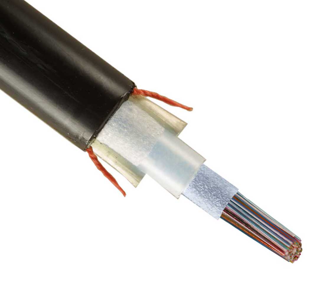
The newest member of the OFS outside plant (OSP) rollable ribbon fiber optic cable line, the AccuRoll DC RR Cable offers twice the fiber density of comparable, standard flat ribbon cables in a smaller and lighter-weight cable. And, this cable is the first and only central core rollable ribbon design that features familiar linear strength elements and a protective central core tube. This core tube delivers enhanced safety for the rollable ribbons beyond that offered by other flexible ribbon cables.
What Are Rollable Ribbons? The AccuRoll DC RR Cable features rollable ribbons, the most exciting technology breakthrough in OSP cabling in years. This technology literally doubles the density of a fiber optic cable while reducing that same cable’s size and weight.
Rollable ribbons are formed by partially bonding individual 250 micron optical fibers to each other at predetermined points. These flexible ribbons can be rolled into very tight bundles for twice the density. Inside the fiber optic cable, rollable ribbons behave much like traditional ribbons, allowing highly efficient splicing using traditional flat ribbon splicing machines and procedures. The rollable ribbons can also be easily broken out into single or multiple fibers and routed.
Available with 144 to 432 fibers in both metallic and dielectric designs, there’s an AccuRoll DC RR Cable to meet the needs of your application. These fiber optic cables are an excellent choice for connecting data centers or in underground, direct buried, and lashed aerial deployments.
Think about it: doubling your network’s fiber density means doubling your transmission capacity, doubling your capability, and doubling your ability to get the job done.
Searching for an innovative fiber optic termination tool or kit? Then look no further: the FITEL EZ-Terminator tool is here.
The newest member of the FITEL Connectivity Solutions portfolio, the EZ-Terminator connector termination tool uses a simple, one-step operation and user-friendly interface to achieve the highest-quality terminations, quickly and under the most demanding conditions.
This handheld connector termination tool combines portability with a ruggedized body to provide the maximum accessibility and powerful performance needed for use in Multiple Dwelling Unit (MDU) and Single-Family Unit (SFU) installations. In addition, the EZ-Terminator tool’s industry-first, patented, removable V-groove allows easy cleaning and optical maintenance.
User-Friendly Design – The wide operation chamber offers easy optical fiber loading and connector assembly;
Simple Operation – The design allows one-touch operation and pre-installed programs for error-free SOC fiber termination projects;
Excellent Visibility – Three LED lights illuminate the entire operating chamber with more than 300 Lux. This intense bright light is critical to performing connector terminations in low-light environments.
Industry-First, Patented, Removable V-Groove – The industry’s only removable V-groove makes cleaning and optimal maintenance easy to achieve in only minutes and with no tools. This capability reduces downtime and supports optical performance.
Combined with a variety of EZ!Fuse™ SOC Components, the EZ-Terminator connector termination tool helps to save both time and money by delivering optical loss performance and yields that substantially surpass those of currently-available mechanical connectors. And, on top of this, the large battery capacity can achieve 100 termination/heating cycles on a single charge, providing installers with portability without sacrificing performance.
The EZ-Terminator connector termination tool’s simple, error-free operation and powerful, consistent performance make it a must-have for any fiber termination project where the highest-quality, repeatable results are critical.
Combining plenum-rated materials with OFS rollable ribbons creates a very compact, yet robust and fiber-dense cable. By featuring rollable ribbons, the latest OFS optical fiber technology, the R-Pack RR Backbone Cable offers twice the fiber density when compared to a traditional flat ribbon premises cable. The result is a reduced diameter, fiber-dense cable that helps customers to substantially improve fiber routing and save on space in congested pathways.
What are Rollable Ribbons?
To form rollable ribbons, 250 micron fibers are partially bonded to each other at intermittent points. Rollable ribbon cables offer the advantages of both loose fibers and traditional flat fiber ribbons in one fiber optic cable. These ribbons can be rolled and routed similarly to individual bare fibers and can also be spliced like traditional fiber ribbons. Rollable ribbons promote efficient and cost-effective mass fusion splicing while also offering easy breakout of individual fibers. These capabilities can help simplify cable installation, save on splicing time and costs and get a new data center or building deployment up and running quickly.
Versatile Cable
While the R-Pack RR Backbone Cable meets stringent Telcordia GR-409 standards for horizontal backbone applications, its plenum construction also meets NFPA 202 requirements for use in a number of demanding building applications, such as routing through ladder racking and raceways. This fiber optic cable can also be used in numerous other application spaces or even to construct assemblies.
Featuring 24, 48 or 72 optical fibers in a versatile design, the R-Pack RR Backbone Fiber Optic Cable is a natural choice for use in Data Centers, Central Offices and Fiber-to-the-Business applications.
A huge increase in digital devices, cloud computing and web services have helped fuel the tremendous demand for increased bandwidth while also pushing datacom rates to 100G and beyond. With these faster speeds and greater use, system designers might assume that single-mode optical fiber holds a growing advantage over multimode optical fiber for premises applications. However, it’s critical to remember that increased Ethernet speeds don’t necessarily mean that single-mode fiber is the best choice.
While it’s true that single-mode fiber holds bandwidth and reach advantages, especially for longer distances, multimode fiber easily supports most distances needed by data center and enterprise networks, and at a significant cost savings over single-mode fiber.
What’s the Difference?
These two optical fiber types were primarily named for the different ways that they transmit light. Single-Mode optical fibers have a small core size (less than 10 microns) and allow only one mode or ray of light to be transmitted. These fibers were mainly designed for networks that involve medium to long distances, such as metro, access and long-haul networks.
On the other hand, multimode fibers have larger cores that work to guide many modes at the same time. These larger cores make it much easier to capture light from a transceiver, helping to control source costs.
Today, network designers and end users can choose from OM3, OM4 or OM5 grades of 50 micron multimode fibers. At one time in the 1980s, as data rates increased, 62.5 micron fiber was introduced because it allowed for longer reach to support campus applications. However, with the advent of gigabit speeds, users moved back to 50 micron fiber with its inherently higher bandwidth. Now 50 micron laser-optimized multimode OM3, OM4 and OM5 fibers offer major bandwidth and reach advantages for short-reach applications along with low system costs.
The Future
Industry standards groups such as IEEE (Ethernet), TIA, ISO/IEC and others continue to recognize multimode optical fiber as the short-reach solution for next-generation speeds. In fact, TIA issued a new standard for the next generation of multimode fiber called wide band (OM5) multimode fiber. This new version of 50 micron fiber can transmit multiple wavelengths using Short Wavelength Division Multiplexing (SWDM) technology, while maintaining OM4 backward compatibility. This capability lets end users gain greater bandwidth and higher speeds from a single fiber by simply adding wavelengths. The OFS version of this fiber is LaserWave® WideBand (OM5) Optical Fiber.
In Short…
Generally, 50 micron optical fiber continues to be the most cost-effective choice for enterprise and data center use up to the 500-600 meter range. Beyond that distance, single-mode optical fiber is necessary.
The OFS LaserWave FLEX Multimode Optical Fiber family offers full performance range and has better optical and geometric specifications than standards require. However, if the network’s transmission distance requires the use of single-mode optical fiber, consider bend-insensitive, zero water peak (ZWP) full-spectrum fibers such as the OFS family of AllWave® Optical Fibers.
Making an overseas phone call? Using cloud computing? If so, there’s a 99 percent chance your call or message is being carried by an undersea fiber optic cable.
Now, new research with lasers may let service providers “push” even more data through these cables to help meet the booming demand for transmission between North America and Europe. In fact, this new method could even increase network capacity without requiring new ocean cables, which can cost hundreds of millions of dollars to manufacture and install.
Setting A New Standard
A research team from Infinera has set a new efficiency standard for transatlantic fiber optic cables. Testing 16QAM modulation – a new approach to transmitting light signals — the group not only shattered efficiency records for data transfer. They nearly doubled data capacity and approached the assumed upper limit for this type of transmission.
The team managed to extend record-setting capacity across the Atlantic Ocean using the MAREA transatlantic cable. This cable spans approximately 4,104 miles (6,605 kilometers) from Virginia Beach, Virginia, to Bilbao, Spain. Partially funded by Facebook and Microsoft, MAREA now holds the record for the highest-capacity cable crossing the Atlantic Ocean.
Skyrocketing Demand
The need for new and better optical fiber and fiber optic cables has constantly grown since the first undersea trans-Atlantic cable was installed back in 1858. Because of the move to cloud-based computing, that demand has skyrocketed over the past decade.
It’s important to note that while this was the first time that PM-16QAM signals were sent over this distance, the team combined equipment readily available to the industry with high-speed lasers to make the transmission. The team generated signal speeds reaching 26.2 terabits per second, a 20 percent increase over what cable developers believed was possible.
Even More Good News
This experiment delivered results much the same as next-generation chip sets from other vendors that use a different technique called probabilistic constellation shaping (PCS). According to the research team, the good news for service providers is that the new technique can be combined with PCS for even faster speeds in the future.
The group presented their research results at OFC 2019 in San Diego.
The National Physical Laboratory (NPL) recently conducted photonics research that may lead to new quantum technologies and telecom systems. The researchers discovered unexpected qualities in light that could, in the long term, lead to completely new electronic devices and applications.
Light is frequently used in electronics involved in telecommunications and computing. One good example of this is how light is used in optical fiber. Optical fiber and fiber optic cables are used to transmit many types of communication around the world, including telephone calls and internet connections.
As mentioned in Physical Review Letters, the NPL researchers studied whether and how light can be controlled in an optical ring resonator. This resonator is a tiny device that can store extremely high light intensities. In an optical ring resonator, wavelengths of light resonate around the device. A comparison would be how some “whispers” can travel around a “whispering gallery” and be heard on the other side.
In a first-ever study, the researchers used optical ring resonators to pinpoint the interaction of two kinds of spontaneous symmetry breaking. The team displayed new ways to manipulate light by (1) studying how time varied between pulses of light and (2) how the light was polarized.
Typically, light follows what is called “time reversal symmetry.” This principle means that if time is reversed, light should return to where it started. However, in the NPL research, at high light intensities, symmetry was broken within the optical ring resonators. A lead scientist on the project noted that, when the ring resonator was seeded with short pulses, the circulating pulses inside the resonator would arrive either before or after the seed pulse. However, they would never arrive at the same time. This discovery could be potentially used to combine and rearrange optical pulses in telecommunications networks.
The researchers also learned that light can suddenly change its polarization in ring resonators. A related example would be you picking a guitar string in a vertical direction, but then having the string begin to vibrate in either a circular clockwise or counter-clockwise direction. The researchers believe that the results of these experiments will not only help to direct the development of improved optical ring resonators (such as for atomic clocks for exact time-keeping). They also feel that these findings will also help scientists to understand how they can control light in photonic circuits in sensors and in quantum technologies.
According to Pascal Del’Haye, NPL Senior Research Scientist, “Optics have become an important part of telecom networks and computing systems. Understanding how we can manipulate light in photonic circuits will help to unlock a whole host of new technologies. These include better sensors and new quantum capabilities, which will become ever more important in our everyday lives.”
You panic when even a few drops of water fall on your laptop. Everyone knows that water and electronics don’t “mix.” That’s why it seems so ironic that most of the Internet’s “hard” infrastructure lies underwater on the ocean floor.
Installing submarine fiber optic cables deep on the ocean floor is time consuming and expensive. While special ships deploy the cable, ocean divers repair and maintain the network. And even with thick, protective jackets, there are many ways to damage a cable. Some destructive forces include ship anchors, commercial fishing equipment, earthquakes, hurricanes and even sinister interference. (more…)
There’s been lots of excitement and even some “hype” around the idea of 5G. But what is it really? Does it mean just faster internet? Will it really be that much better than 4G? Many people are asking these questions as the FCC begins to auction the first licenses for the airwaves that will carry 5G service.
What Is 5G, Really?
5G will be up to 100 times faster than today’s cellular connections – and even faster than many home fiber optic broadband services. But it’s not just about speed. Networks will have greater capacity and respond faster than earlier wireless services. More people and devices will work at the same time on the same network without slowing it to a crawl. And it will do all of this with lower latency. Latency is the time delay between a device contacting the network and receiving a response.
This improved latency will help to bring about some of the most amazing tech trends on the horizon. And while 5G may not change your life right away, it will certainly bring some totally new technologies to life. For now, here are a few of the most exciting apps and technologies that 5G will enable.
Promising 5G Applications
Self-driving vehicles – Self-driving cars will be a common sight with the next generation of wireless service. And 5G will make vehicle-to-vehicle communication happen – where cars can almost instantly share information between them on their location, speed, acceleration, direction and steering. Many experts believe that this feature will become the greatest lifesaving advance in the auto industry in more than a decade. Using this, cars will know before their drivers when another car moves into your blind spot or when a dump truck that’s six vehicles ahead suddenly stops.
Telesurgery – Remote surgery isn’t new. However, 5G could make a huge difference in providing medical care to millions in distant locations, along with training doctors remotely in surgery and other specialties.
Virtual Reality – For truly realistic virtual reality (VR), a wireless network must carry tons of data. And while it must be fast, the network must also handle this data deluge to create a life-like VR experience. It will take 5G to make this happen.
Drones: 5G technology will let drones talk to one another, helping prevent overhead accidents while in flight.
5G wireless networks can make many of the technologies, applications and experiences that we’ve been waiting for a reality.

 Searching for a highly-dense fiber optic cable solution with a familiar, cost-effective central core design? Then look no further than
  Searching for an innovative fiber optic termination tool or kit? Then look no further: the
 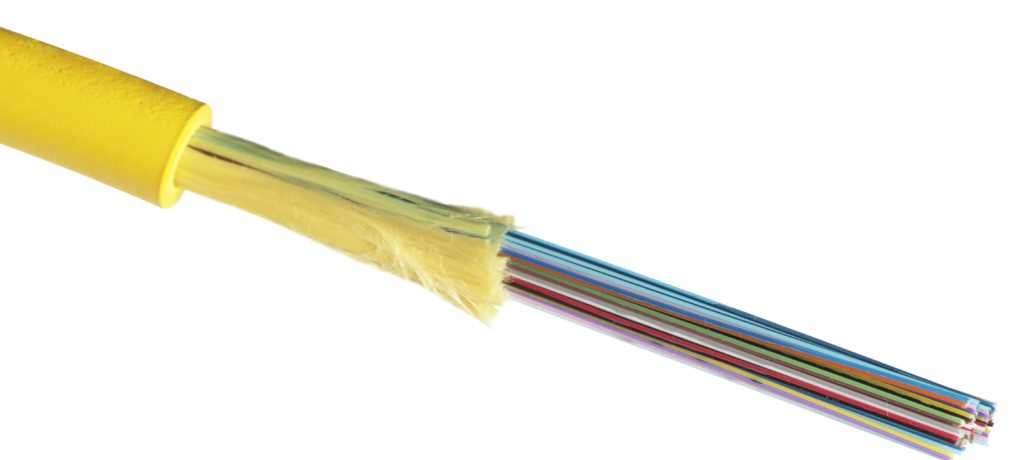 When you need a fiber-dense yet compact cabling solution for high-bandwidth, high-density applications, look to the
 The National Physical Laboratory (NPL) recently conducted photonics research that may lead to new quantum technologies and telecom systems. The researchers discovered unexpected qualities in light that could, in the long term, lead to completely new electronic devices and applications.
 You panic when even a few drops of water fall on your laptop. Everyone knows that water and electronics don’t “mix.” That’s why it seems so ironic that most of the Internet’s “hard” infrastructure lies underwater on the ocean floor.
 There’s been lots of excitement and even some “hype” around the idea of 5G. But what is it really? Does it mean just