This article focuses on the parameters that affect available bandwidth in optical fibers, and the dispersion mechanisms of various fiber types and non-linear effects. Dispersion describes the process of how an input signal broadens out as it travels down the fiber. There are several types of dispersions that we will cover. We’ll also take a cursory look at other important nonlinear effects that can reduce the amount of bandwidth that is ultimately available over an optical fiber.
Dispersion
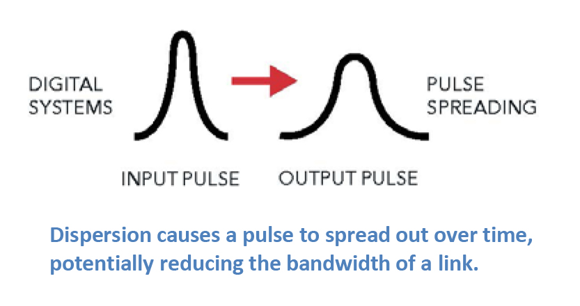
Most of the traffic traveling through fiber networks takes the form of a laser pulse, where the laser is pulsed on and off, effectively forming a digital square wave comprised of “1”s and “0”s. Dispersion causes a pulse to spread out over time, effectively rounding the edges, and making it harder for the detector to determine whether a “1” or a “0” is being transmitted. When this happens, the effective bandwidth of the link is reduced. The three main types of dispersion mechanisms are modal dispersion, chromatic dispersion, and polarization mode dispersion. Because these mechanisms affect fiber networks in different ways, we’ll discuss each in some depth. Please download the full article for more information.
Modal Dispersion
In general, our article on Single-Mode Optical Fiber Selection focuses on single-mode fibers since they comprise the vast majority of fiber kilometers deployed around the world. In contrast to multimode fibers, single-mode fibers are used for all high-capacity, long-distance networks due to their low attenuation and high bandwidth. A main limiting factor of multimode fibers is modal dispersion.
>> Download the full Article
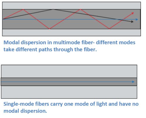
Multimode fibers carry multiple modes of light at the same time. While a mode of light can be thought of as a ray of light, a typical multimode fiber can have up to 17 modes of light traveling along it at once. These modes all traverse slightly different paths through the fiber, with some path lengths longer than others. Modes that take a straighter path will arrive sooner, and modes that bounce along the outer edges of the core of the fiber take a longer path and arrive later. The effect on the end pulse is called modal dispersion, since it is due to the different modes in the fiber. Multimode fibers are designed to reduce the amount of modal dispersion with precise control of the index of refraction profile, through the quantity of dopants used in the core. However, it isn’t possible to completely eliminate modal dispersion in multimode fibers.
Chromatic Dispersion
Chromatic dispersion describes a combination
of two separate types of dispersion, namely material dispersion and waveguide
dispersion. Light travels at different speeds at different wavelengths, and all
laser pulses are transmitted over a wavelength range. Light also travels at
different speeds through different materials. These varying speeds cause pulses
to either spread out or compress as they travel down the fiber. Fiber designers
can use these two points to customize the index of refraction profile to
produce fibers for different applications. Chromatic dispersion isn’t always a
bad thing. In fact, it can be used as a tool to help optimize network
performance.
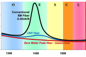
For example, the first lasers used for fiber
transmission operated at 1310 nm, and many networks still use that wavelength.
Fiber designers therefore developed the first single-mode fibers to have
minimum or zero dispersion at this wavelength. In fact, G.652 fibers are still
designed this way. In these fibers, dispersion is higher in the 1550 nm window.
Today’s networks often operate with multiple
wavelengths running over them. In these networks, nonlinear effects that result
from the multiple wavelengths can affect network operation. We’ll give a brief
overview of some of these non-linear effects in this article. Chromatic
dispersion is often used as a tool to help optimize these types of networks.
Polarization Mode Dispersion (PMD)
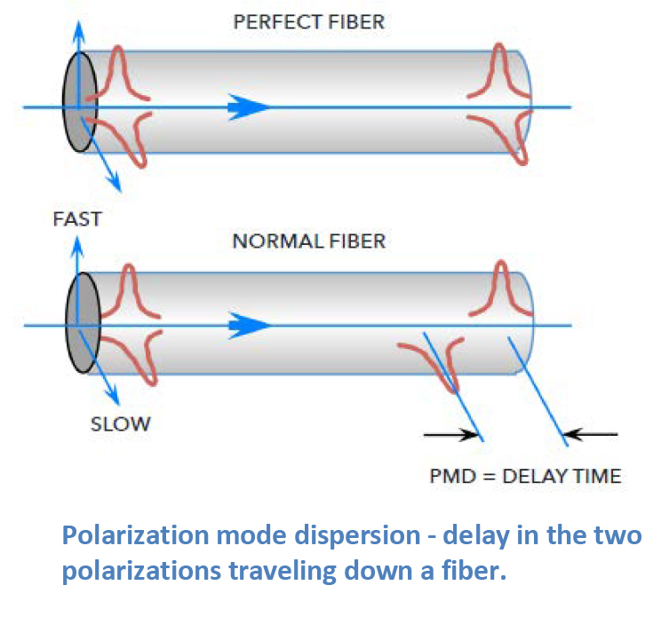
Light is an electromagnetic wave and is comprised of two polarizations that travel down the fiber at the same time. In a perfectly round fiber deployed with perfectly balanced external stresses, these polarizations would reach the end of the fiber at the same time. Of course, our world isn’t perfect. Even small amounts of glass ovality/non-concentricity or non-concentric stresses in the cable can cause one of the polarizations to travel faster than the other, spreading out in time as they travel along the fiber. This phenomenon is called polarization mode dispersion (PMD).
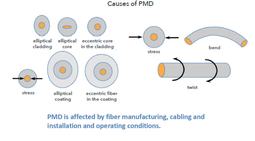
Cabling and installation affect PMD, and even
things like vibration from trains moving down tracks or wind-induced aerial
cable vibrations can affect PMD. However, the impacts of these interactions are
typically smaller than the inherent PMD caused by the glass manufacturing
process.
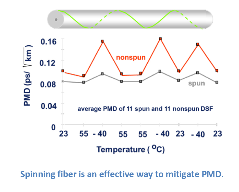
There are ways to mitigate PMD. One very
effective method is to make the glass fiber as geometrically round and
consistent as possible. OFS uses a special technique to accomplish this. Using
a patented process called fiber “spinning”; half-twists are translated through
the fiber during the draw process, reducing the non-concentricities and
ovalities in the glass that are the major contributors to increased PMD.
>> Download the full Article
Non-Linear Effects
There are a host of other factors that
network, equipment, and fiber designers have needed to consider as network
capabilities have grown over the years. These factors often result as we
collectively add more and more wavelengths of traffic at greater speeds and
higher power levels.
It is not the intent of this article to review
each of these in depth, but instead to touch on them so the reader can have a
passing familiarity. The highest profile of these factors is four-wave mixing,
which led to the development of non-zero dispersion-shifted fibers (NZDF).
However, other non-linear effects include self-phase modulation, cross-phase
modulation, Raman and Brillouin scattering, and others. As mentioned earlier,
chromatic dispersion can be used to offset the effects of four-wave mixing. For
those non-linear effects related to higher power levels, increasing the
effective area where the light travels down the fiber can help to reduce the
impact of these other non-linear effects.
Dispersions and non-linear effects are the
least understood issues in the general fiber user population, mainly because
the guidelines used to match up today’s fibers and electronics typically work
so that the end user doesn’t need to have a detailed background to bring up a
system.
OFS has multiple decades of experience with fiber optic networks. Please contact your local OFS representative if you would like additional information regarding any of the items in this article.
>> Download the full Article
OFS is a market leader in the design and manufacture of standard and custom Dispersion Slope Compensating Modules (DSCMs) also known as Dispersion Compensating Modules (DCMs). Our fixed broadband, reconfigurable, and tunable colorless modules round out a product line that is well-suited for the major transmission fiber types.
Already known as the state’s first gigabit city, Wilson, North Carolina, is now also that state’s first city to offer a “Fiber Optics Basics” training course at its local community college. Last month, Wilson Greenlight, the city’s community-owned, fiber-to-the-home provider, partnered with Wilson Community College to launch the pilot 10-week program.
A Long-Held Dream
The fiber optic training course is the answer to a long-held dream for Gene Scott, Wilson Greenlight’s director of outside plant. Frustrated by having highly-skilled jobs to offer that he could not fill, Scott found that standard fiber training courses cost thousands of dollars that few young people could afford.
Experts Share Knowledge/Expertise
Visiting experts from around North Carolina and the U.S. are volunteering to teach their specialty. For example, OFS expert Mark Boxer is teaching three classes covering topics ranging from the history of light wave transmission to the design of various fiber optic networks.
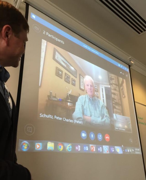
In one of these classes, Boxer featured a very special guest, Dr. Peter Charles Schultz. Dr. Schultz is a co-inventor of fiber optics and the recipient of the National Medal of Technology and Innovation presented by President Bill Clinton (the highest technology award of the U.S. Government). Dr. Schultz also serves as a senior advisor to and board member of OFS. During the class, Dr. Schultz described his experiences in developing fiber optics, something that few people at the time understood or valued. When asked his advice to others who might seek to blaze a new trail in the digital frontier, Schultz answered, “Be brave!”
Training for Today and Tomorrow
Other courses in the program range from how to prepare, splice and connect fiber optic cables to fiber optic safety. Instructors will expose students to various types of fiber networks, the basics on how to design a fiber-to-the-home network, how to maintain outside plant infrastructure and even how to budget and read engineering design prints.
The long-range plan is to offer a two-year partnership between a local high school and the community college. Students would leave high school with a two-year certificate in an advanced degree and qualify for higher-paying jobs after graduation. One added advantage would be to pique students’ interest in tackling a four-year college degree in new fields like fiber network management
 Engineers at the California Institute of Technology have created the world’s smallest fiber optic gyroscope to aid in navigational sensing. Five hundred times smaller than a regular gyroscope, this new gyro can fit on a grain of rice. This research breakthrough could lead to more accurate fiber optic gyros compared to mechanical units.
WHAT OPTICAL GYROS DO
Advanced fiber optic navigation technology is critical for aircraft, missiles, unmanned aerial vehicles and ground vehicles. These machines and other platforms depend on fiber optic gyroscopes to operate safely.
HOW THEY DO THEY WORK?
A fiber optic gyroscope detects changes in position or direction using the Sagnac effect. In this way, an optical gyro functions similarly to a mechanical gyro. However, the optical gyro operates by using light passing through a coil of optical fiber.
Inside a typical optical gyroscope, a spooled-up optical fiber carries pulses of laser light. Some pulses move clockwise and others go counterclockwise. The gyro measures rotation by detecting tiny changes in how these pulses arrive at a sensor. Researchers have tried to create smaller optical gyros. However, as the size of the gyro shrinks, the signals from its sensor have grown weaker until they are drowned out by “noise” from scattered light.
WHAT THE TEAM DID
The Cal Tech research team designed a low-noise, photonic gyroscope. They etched light-guiding channels onto a two-square-millimeter silicon chip. These channels guide the light in each direction around a separate circle. This layout keeps scattered light from confusing the device’s sensors. The new design also reverses the light’s direction from time to time. This change helps to cancel out much of the related “noise.”
Optical gyroscopes that use the Sagnac effect to measure rotation could eventually be miniaturized onto nano-photonic platforms. However, thermal fluctuations, component drift and fabrication mismatch often limit the signal-to-noise ratio of these gyros. Because a microscale unit would have a weaker signal, researchers have not yet created an integrated nano-photonic fiber optic gyroscope.
Download our Fiber Optic Gyroscope Application Brochure
Learn more about SMM-D1310B FIBER 200kpsi Fiber
We also make aerial fiber optic cable for flight communication systems.
With the growing need to accurately monitor processes in harsh environments, optical fibers are becoming an essential element within monitoring systems, both as the communications line and as the sensing element. Optical fiber sensors have been widely adopted and used in pipeline monitoring, perimeter monitoring, heat detection and structural monitoring systems, all of which operate within the typical 45 °C to 85 °C temperature range of a standard optical fiber.
However, as industries push their sensing requirements into environments such as those found in oil wells (for downhole measurement) and nuclear reactors, there is a need for optical fibers that can tolerate these extremely high temperatures and challenging environments.
Specifically developed for harsh temperature sensing and communications environments, the new PYROCOAT K Optical Fiber is up to the challenge. This mechanically-strong fiber features an improved coating that provides excellent thermal stability, enabling wider operating temperatures than other commercially available polymer-coated fibers. In fact, the PYROCOAT K Optical Fiber provides reliable performance even when subjected to extreme, long-term, high temperature exposure. (more…)
Over the past 30 years, optical fiber and fiber optic cable have become increasingly durable and user friendly. At the same time, the use of fiber optics has exploded with many more workers now handling both fiber and cable.
However, while these individuals may understand the How-Tos of optical fiber, they may lack knowledge of the essential fiber optic Whys. To learn these critical rules, you must become a full-fledged “Fiber Geek.” And, because technology and applications are rapidly evolving, achieving true “fiber geekdom” is an ongoing process.
This first in a series of articles will help readers understand some secondary fiber specifications to begin climbing the “Fiber Geek” ladder. In this article, we focus on the continuing demand for bandwidth and how the need for even greater bandwidth is on the horizon. In addition, we also examine ways that this need can be satisfied. Finally, we consider the importance of industry standards in setting network performance levels..
To access this article and begin the journey toward becoming a “Fiber Geek,” please go here.
Data centers and enterprise networks continue to require ever-increasing speeds. Yesterday’s 10 Gbps networks are rapidly being replaced by 40 and 100 Gbps speeds, and 400 Gbps networks are on the horizon. How can today’s network designers best support this increasing demand for bandwidth?
TIA has standardized a new multimode fiber to support short wavelength division multiplexing (SWDM). Referred to in the industry as “wideband” multimode optical fiber, this new fiber type extends the ability of conventional OM4 fiber to support multiple wavelengths. Wideband optical fiber will maintain the cost advantages of multimode fiber for short-distance applications by supporting duplex fiber links at speeds up to 100 Gbps and 400 Gbps eight-fiber links.
OFS’ LaserWave® FLEX WideBand Multimode Optical Fiber is designed to support today’s high speed 850 nm-based systems and tomorrow’s multi-wavelength systems. Optimized for SWDM, OFS WideBand Optical Fiber is the best choice for short-reach enterprise and data center applications.
For the latest WHITE PAPER on LaserWave FLEX WideBand Optical Fiber, please go here.
As data centers increase in size and scale, many industry watchers wonder when the use of single-mode optical fiber will overtake multimode fiber in these facilities. For hyperscale data center designers, that time has arrived. However, for much of the enterprise market, multimode fiber still offers significant cost and power savings over other fibers for supporting short-reach links.
As you read this blog, multimode fiber developers are hard at work creating even more cost-effective, short-reach solutions. In fact, fiber manufacturers recently introduced OM5 wideband multimode fiber, which will support short wavelength division multiplexing (SWDM).
In a new ICT Today article, OFS Product Manager John Kamino takes an in-depth look at the evolution, introduction and standardization of wideband multimode fiber.
Data traffic on optical and mobile networks, video streaming and the large-scale rollout of Cloud computing continue to increase each year. This tremendous growth is creating the demand for additional capacity and placing stress on existing long-haul optical networks.
To help meet this need, OFS has designed and introduced a new G.654.B compliant optical fiber. This award-winning fiber combines Ultra-Low Loss with an optimized effective area that is 49% larger than the effective area of standard G.652.D fiber. As a result, network operators can maximize the distance between signal amplification and regeneration sites which, in turn, helps to reduce the overall system costs of long-haul networks.
Dr. Peter Weimann of OFS will present a live webinar on March 17, sponsored by IWCS, to discuss this new Ultra-Low Loss Fiber for terrestrial applications.
Recent activity in the TIA TR-42 Engineering Committee produced multiple standards affecting the specification, design, installation and management of fiber optic cabling components and systems.
To help providers understand these changing standards, Product Manager John Kamino will take center stage in a webinar sponsored by Cabling Installation and Maintenance on October 27, 2016. During this session, John will discuss topics including the ANSI/TIA-492AAAE Standard for Wideband Multimode Fiber and revisions in the TIA-942-B standard for Data Center Cabling.
To learn more and register for this webinar, please visit HERE.


 Engineers at the California Institute of Technology have created the world’s smallest

 Data traffic on optical and mobile networks, video streaming and the large-scale rollout of Cloud computing continue to increase each year. This tremendous growth is creating the demand for additional capacity and placing stress on existing long-haul optical networks.