We use cookies to help us provide you with a more enhanced and personalized experience adapted to your interests. By using our site you agree to our Terms of Use and Privacy Policy, including our use of cookies.
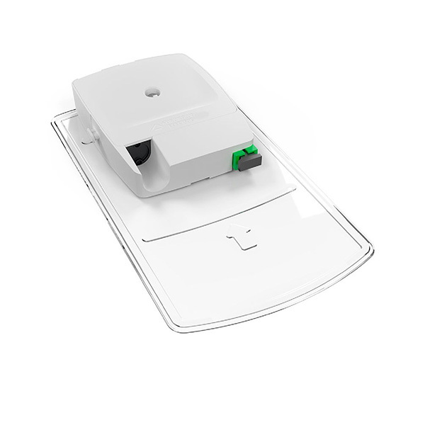
Hi, I’m John George, Senior Director of Solutions Engineering and Fusion Splicers at OFS. What’s new in my world is our new MDU!Click® Solution for fiber deployment in buildings.
With the MDU!Click Solution we can defer the cost of a splitter module until we have a higher take rate on each floor. This is for a pay-as-you-grow kind of deployment. It’s used for a second, or third entrant into the building, fiber to the business deployments, or maybe high take rates aren’t expected initially and there’s a desire to defer the cost of the build as much as possible with subscriber growth.
The way the system works is we have a MDU!Click SlimBox® Flex Indoor Module in the MDF the entry point of the building with a one by four or one by eight splitter feeding through the EZ-Bend® 12 or 24 fiber riser cable. You can see this is a very compact cable that can fit in limited spaces. We’re breaking out a single fiber so we can support one subscriber per floor in the initial deployment. Then, we can connect that first subscriber by plugging in one of our EZ-Bend Jumpers – a drop cable assembly that can go many hundreds of feet if needed.
The EZ Bend cable has a 2.5 millimeter bend radius to handle the cornering in the buildings that’s often required. Then, to add more than one subscriber on each floor, we simply put in place our MDU!Click SlimBox Flex Indoor Splitter Module and expand from one to eight ports. We can reconnect our initial subscriber and connect seven more subscribers on that floor, in order to get a higher take rate as we get new subscribers in the building.
That’s what’s new in my world, the MDU!Click® Solution for fiber in the building.
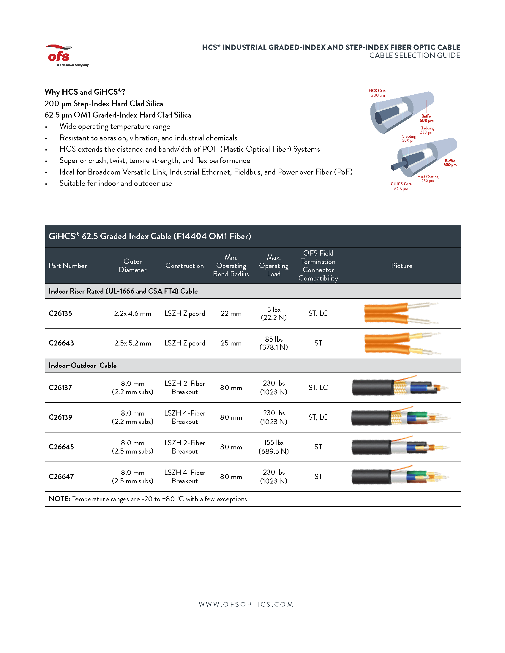
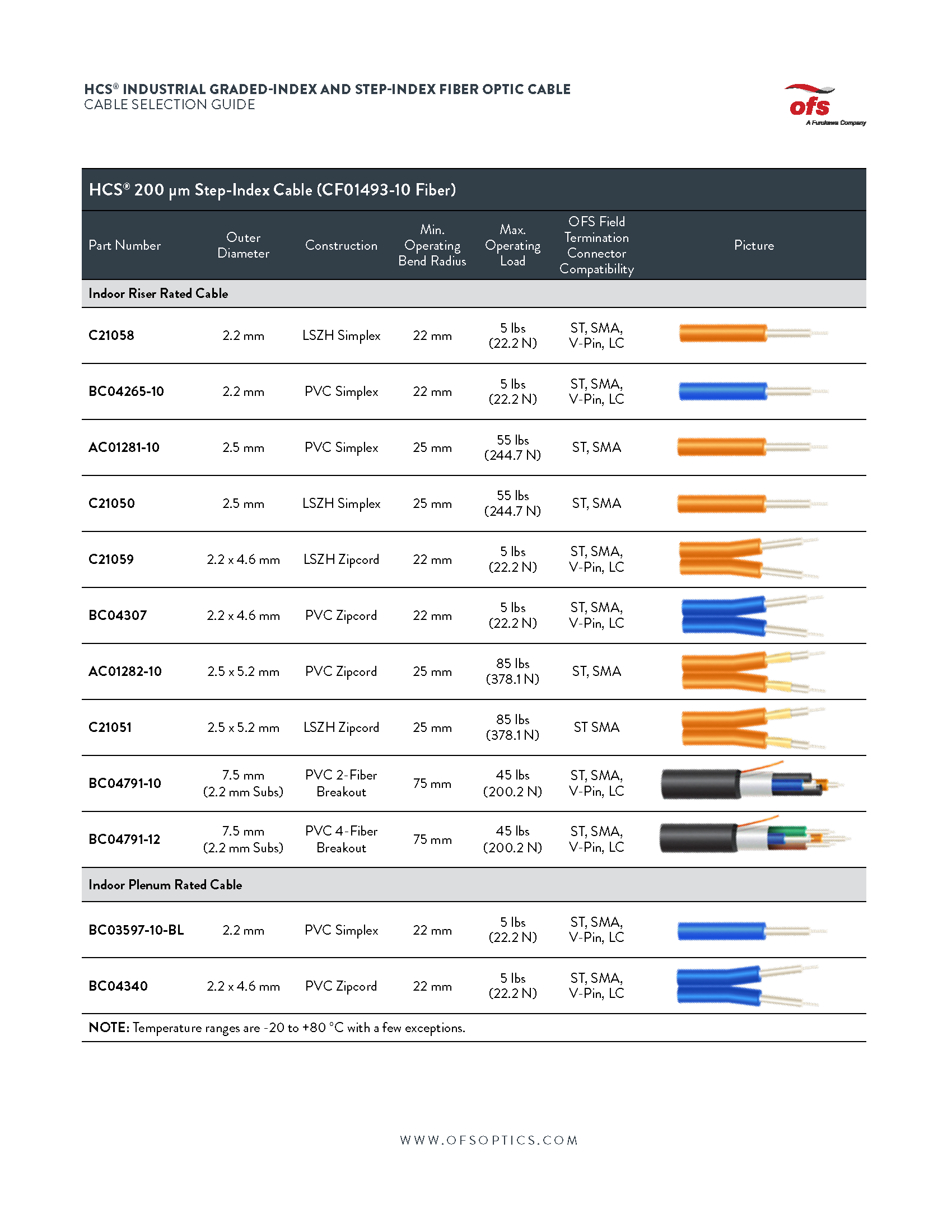
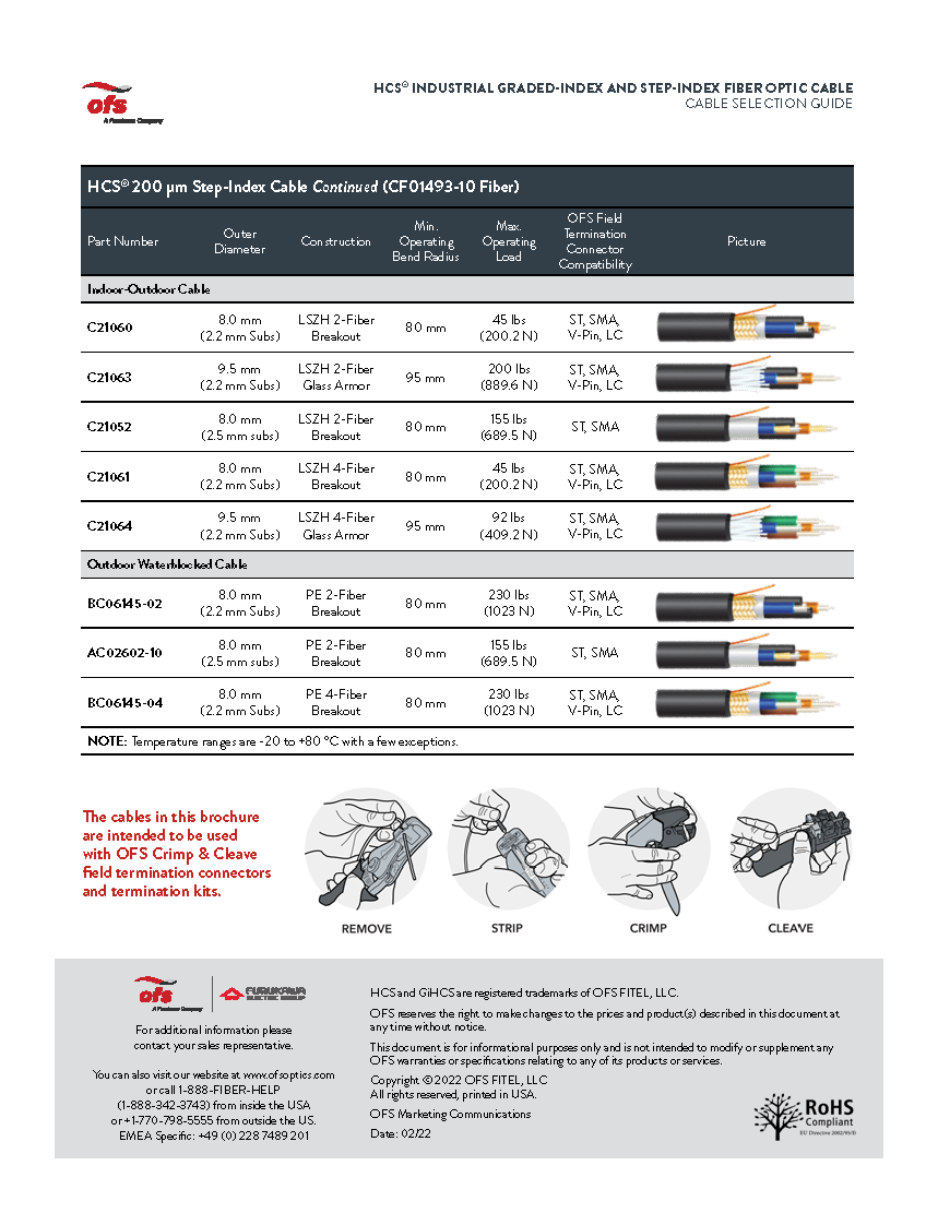
HCS® Industrial Graded-Index and Step-Index Fiber Optic Cable Selection Guide
Indoor and outdoor optical fiber cables for use in Substation Automation, Factory Automation, Industrial Ethernet, HVDC Systems, and Power Electronics.
When you’re trying to decide on which fiber optic cable to choose for an application. You have many choices of various constructions and fiber types of as has made this step easier for you. With the help of our new cable selection guide, which consists of cables for industrial applications, what the selection guide is designed to do is to make your job easier to determine the most appropriate and cost-effective cable for your project or installation. The selection guide is going to focus on the office industrial multimode fiber optic cables that are designed for, and common in, many factories and substations, as well as other harsh environment applications.
For those of you who work in industrial environments, whether it be a steel mill, paper mill, a substation, or any type of harsh environment, the HCS product line is ideal for you for many reasons. Unlike traditional fibers, the primary fiber coating makes bonds to the fiber and enhances the strength during the draw or production process. Additionally, because the coating remains on the glass during the termination process, the fiber maintains its inherent strength. This makes it unique in that there is never bare glass exposed to the environment such as humidity, dirt, and dust. Those environmental factors are all known to detract from the strength of the fiber optics. When you’re considering the product line, here’s what you’re getting a rugged and robust construction resistance to abrasion in industrial chemicals. Reliable and repeatable termination process. A short learning curve for terminations. So selection considerations include extreme temperatures of Florida, Arizona, to the frigid temperatures of the Canadian tundra or Alaska. Humidity also plays a factor in states like Texas and Louisiana. You will also consider installation pull strength, the compressive strength of the cable. What kind of weight can the cable bear during the installation?
The first page here we have 62.5 micron cables, which are indoor zipcord cables for data center type applications. Indoor outdoor cables which can be used for either these are breakout cables and all the outdoor cables will have a water block in the cable as well as some of them will have a glass armor for road and deterring because you’re going to deter the road they’re trying to chew through the cable.
And looking at our 200 micron step index cable from simplex to zip cords to breakouts through indoor applications, we have riser rated we have plenum rated, we have indoor outdoor cables. And we also have cables that are designed strictly for outdoor applications. Again, with the water block, as you see at the bottom here, we have a schematic which shows the termination process of a typical O of this connector.
First, we’re going to remove the cable jacket, then we’re going to strip the fiber. Then we’re going to crimp the connector on, and then we’re going to cleave the glass. And for a pristine finish on the end of the connector. What I’ll do in my next talk is share with you information on the connector systems that go along with the cables we just talked about. And that’s what’s new in my world.
Mark Boxer, OFS Technical Manager, reveals what makes Rollable Ribbon so special. To form these ribbons, fibers are partially bonded to each other at intermittent points. This design not only enables mass fusion ribbon splicing but allows for easier individual fiber breakout than flat ribbons. The preferential bending plane of the rollable ribbons facilitates rolling and routing in smaller closures and splice trays, similar to individual fibers.
Hi. I’m Mark Boxer with OFS. Today I’d like to talk about Rollable Ribbon and if you haven’t seen it before, it is this stuff, so it’s pretty neat. It collapses upon itself when it’s rolled into a tight cylinder so you can kind of collapse it.
And then you can also easily separate it out to pull out an individual fiber. So, I’ll do that and get a little bit closer. So you can see that and then it just snaps back into place so you can slice it again. So, it splices like a ribbon. It can be rolled very, very tightly, providing the ability of tight fiber density in a very, very small package.
So, you compare this to a flat ribbon. This is a flat ribbon and so there is no there is no moving of this or no rolling this without breaking the ribbon. So why this is important really comes back to geometry. So, this is an 864 fiber central to flat ribbon cable. So, if you look at it, you can see that there is a lot of space in between the flat ribbons and the tube.
And that’s because we’ve got ribbons that are fundamentally rectangles. And the cable is fundamentally a circle. When you have a circle and a rectangle, then it those don’t fit that efficiently. If you look at a rollable version of this cable with 864 fibers, you can see here there’s not very much space between the fibers and the tube.
And let me go ahead and put both of these side by side. And you can see that this is the flat ribbon 864. This is the rollable 864. Now there’s a significant difference in size between the two.
Rollable Ribbon was dreamed up in Japan back in the 2000’s and went through a development path that was actually similar to the SC Connector that happened in the early 1990s.
And what I mean by that is that NTT in Japan farmed out the concept to various companies who ultimately brought it to market. For the case of Rollable Ribbon OFS parent company, Furukawa was one of those companies that introduced Rollable Ribbon and so we brought it back to brought it to market during the middle part of the 2010’s.
So there are so many benefits to Rollable Ribbon. You know, we see it in a lot of different environments, and I call this the buffet of benefits using Rollable Ribbon. It’s small. The ribbons themselves are very small so they can be rolled. That means that cables can be much smaller and lighter for a given size.
That can gives the ability to fit more fiber into smaller ducts. It can mean smaller hand holds more cable on a real for longer lengths or fewer slice points. And then for aerial installations also since everything’s smaller, also less weight on the pole, less amount of ice to build up. Smaller in general typically makes things easier. Some customers like it because it can be placed in thinner slice trays enabling more trays and a closure or a smaller closure for a given fiber count.
All of these cables are gel free, so they’re easier to prepare for slicing. And of course, these are ribbon. So there can be mass fusion spliced 12 at a time. The initial installations were primarily used to connect data centers together because data centers use very high fiber count cables, you know, think of 1728s, 3456s.
But what I’m really excited about is the concept of using rollable ribbons in lower fiber count networks. Including fiber to the home, backbone, and distribution networks. For those applications, we have typically used, lose tube cables in the past because it’s easier to pull out an individual fiber to connect a subscriber. But now with Rollable Ribbon, it’s easier to pick out an individual fiber versus a loose tube. The ribbons or clearly marked, the fiber color is always going to be in the same place. You just basically pick out whatever you need.
So now the cables can be smaller, they can be easier to work with in the field. If you compare these so these 288 fiber count cables. The first is a loose tube. It’s actually pretty big. And this is a flat ribbon cable 288.
So now look at the rollable – and so we’ve got a couple of different versions of this but actually the larger rollable you can see that even the larger rollable is much smaller than either the loose tube or the flat ribbon.
All of these cables are GR20 rated. So you have the same rugged, crush, impact, and tinsel performance that we’ve come to rely on for decades. So give Rollable Ribbon some thoughts for your network. Now you can get the benefits of ribbon slicing when you can use it. Or also single fiber access. You can do either one, whenever or where ever you need to.
It can act as a ribbon. It can also act as a single fiber giving you a lot of freedom to use either platform in a much smaller package.
So overall, we think we’re going to see a lot more customers move towards Rollable Ribbon in their fiber to the home distribution networks. And now in the future.
We invite you on a tour of our fiber optic cable manufacturing facilities in Carrollton, Georgia, USA. View the highly automated OFS manufacturing process that produces a wide variety of fiber optic cables and products for telecommunications applications. Loose tube, microcables, flat ribbon, ADSS, ultra high density rollable ribbon cables and premise cables are all made here.
What is Fiber Optic Cable Made up of?
Fiber optic cables are made up of several components: a core, cladding, jacket, and strength members.
The core is the optical fiber itself which is a continuous strand of ultra-thin glass.
Within the core, there are two highly specialized glass coatings called cladding and jacketing.
The cladding helps bounce back imperceptible light signals as they travel along the cable by reflecting off of its walls.
The jacketing protects the delicate optical fibers from mechanical damage and environmental effects.
Lastly, strength members such as aramid yarns or steel wires are used to reinforce and protect the cable further against bending or stretching forces. Together these components form a fiber optic cable that carries light signals over long distances without signal loss or interference.
The manufacturing facility is registered in compliance with the ISO 9001, ISO 14000, and TL 9000 standards. Traceability is maintained through every step of the process and ultimately back to the incoming fiber. The facility also has a fully functional product qualification lab and cable installation test track.
OFS Uses Both 200 and 250 Micron Fibers
OFS makes several different fiber structures in the Carrollton facility, including loose tube, flat ribbon and rollable ribbon structures. These structures are used in different cable types and applications.
Statistical Process Control Techniques
Each stage in the manufacturing process is highly controlled with appropriate dimensional targets and tolerances.
Colored ink is applied to the Fiber
The industry standard color code is used to provide clear identification of the fibers over their lifetimes. Colored ink is applied to specified thicknesses, cured, and respooled for the next step in the process.
Buffer Tube Manufacturing Process
To make loose tubes, fibers or ribbons are paid off of their spools and a buffer tube is extruded around them. The Carrollton plant makes gel-free and gel-filled buffer tubes of different materials, including polypropylene and PBT. Different sized buffer tubes are used for different product types. Buffer tubes used in outside plant applications include either water blocking materials impregnated with super absorbent polymer or gel.
Ribbon Manufacturing Process
A matrix material is applied to the fibers to bind them together so they can be spliced as a group. 12 and 24 fiber flat ribbons are most common. Fiber color code alignment and geometric specifications are very important so ribbons can be spliced and connected in the field.
Rollable ribbons are only partially bonded together, enabling them to be rolled into a cylindrical package. Rollable ribbons are only partially bonded together, enabling them to be rolled into a cylindrical package. Since circles are more space efficient than rectangles, rollable ribbons cables can hold twice the fibers as comparable sized flat ribbon cables. Since these fibers are partially bonded, they can be easily spliced either as single fibers or as a ribbon, giving more deployment flexibility to the network operator.
Cabling
OFS makes two main types of cables – stranded cables and central tube cables.
Stranded cables are made by stranding tubes of fibers, flat ribbons, or rollable ribbons around a central member. Stranded cables are often used in applications requiring frequent access to fibers.
For direct-buried cables, one or more steel armor layers may be added to provide rodent resistance and toning capability.
Outer Jacket
Different versions of polyethylene are used for the majority of outside plant cables. For inside plant or indoor/outdoor cables, materials are chosen to include appropriate flame and smoke resistance.
Information Printing
Type of cable, date of manufacture, length and a unique serial number that can enable traceability through the manufacturing process is printed.
Final Testing
Once manufacturing is complete, the finished cable undergoes final testing for length and optical properties.
Shipping
Cables are then packaged for shipment and loaded on trucks to their final destination.
This document covers cable placing in conduit, innerduct, handholes, and manhole structures. The innerduct may be direct buried or placed in larger diameter conduits. In some applications, the innerduct may be lashed to an aerial strand.
This document covers conventional cable placing techniques that are used to pull or blow (cable jetting) the cable into the conduit or innerduct.
It is recommended that an outside plant engineer conduct a route survey and inspection prior to cable installation. Manholes and ducts should be inspected to determine the optimum splice locations and duct assignments. A detailed installation plan, including cable pulling or blowing locations, intermediate assist points, and cable feed locations should be developed based on the route survey.
2.2 Maximum Rated Cable Load
The maximum rated cable load (MRCL) for most OFS outside plant fiber optic cables is 600 lb; however, the cable documentation should always be checked because lower values of MRCL may apply for some cables. When using pulling equipment to install cable, measures should be taken to ensure that the MRCL is not exceeded. This includes the use of breakaway swivels, hydraulic pressure relief valves, and electronic tension control systems.
2.3 Minimum Bend Diameter
The minimum bend diameters for OFS cables are defined for both dynamic and static conditions. The dynamic condition applies during installation when a cable may be exposed to the MRCL, e.g., while pulling the cable around a sheave or capstan.
2.4 Temperature Limits
Storage and installation of OFS fiber optic cable is limited to the temperature ranges. Be aware that solar heating due to sunlight exposure can increase the cable temperature well above the ambient temperature.
3. Underground Optical Cable Precautions
Before starting any underground cable placing operations, all personnel must be thoroughly familiar with local company safety practices. Practices covering the following procedures should be given special emphasis:
Fiber optic cable is most often placed in a small-diameter innerduct rather than a large-diameter conduit. For existing conduit structures, multiple innerducts can be placed in a single conduit to provide multiple cable paths in the duct. Innerduct is also recommended because it provides a clean continuous path for the installation of the fiber optic cable.
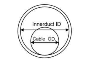
4.1 Diameter Ratio and Area Ratio
Diameter ratio and/or area ratio are used to determine the optimal cable OD that should be installed in an innerduct. Either ratio can be used, but consistently using one or the other is important to avoid confusion.
4.2 Direct Buried Applications
Studies have shown that vertical undulations in direct buried innerduct can greatly increase the required cable installation forces.
5. Cable Lubricant
Cable lubricant should be used when placing fiber optic cables. Recommended cable lubricants include Polywater4, Hydralube5, and similar cable lubricants that are compatible with polyethylene cable jackets. Both the winch line (or pulling rope) and the cable should be lubricated.
The backfeed technique is a common installation method that is used to divide the cable installation into two separate pulls. The backfeed technique may also be used near equipment offices when one end of the cable must be pulled by hand into the building, or at manhole locations where the cable route changes direction.
6.2 Forward-Feed Technique
In the forward-feed technique, the leading end of the cable and excess cable length are pulled out of the innerduct at an intermediate manhole and stored on the ground in a figure-eight. This technique can be used multiple times during a cable installation to greatly increase the distance between cable splices.
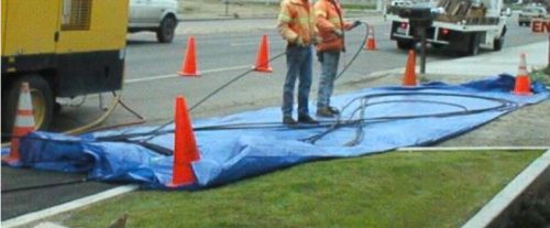
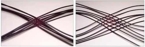
6.3 Figure-Eight Installation Techniques
If figure-eight techniques are used during cable installation, the cable should be handled manually and stored on the ground. Place the cable on tarps to prevent damage from gravel, rocks, or other abrasive surfaces.
When figure-eighting heavy cables (264 fibers or more), the cable stack should be offset to prevent sheath dents and cable damage. Although sheath dents do not typically damage fibers, this type of cosmetic damage is undesirable. When utilizing the offset method, each crossover point of the cable stack should be offset about 2 inches instead of being stacked directly on top of each other.
Standard vs Offset Figure Eight
6.4 Handholes
Handholes are frequently used to provide access to cable splices and slack storage coils. On long cable pulls, handholes may be used to facilitate intermediate-assist placing operations. The intermediate-assist handholes are typically installed near obstacles or at a predetermined spacing that coincides with the maximum expected cable installation length.
7. Pulling Fiber Optic Cable
The following instructions assume general familiarity with outside plant cable placing procedures. They also assume that the innerduct is in place and a lubricated pulling tape or rope has been installed in the innerduct.
7.1 Feed Manhole
Breakaway Swivel Connector
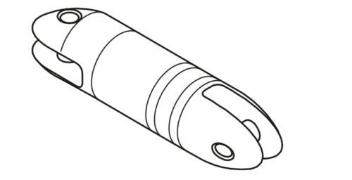
Mount the cable reel on the reel carrier so that the cable feeds off the top of the reel. Position the cable reel adjacent to the manhole and in-line with the innerduct. The cable reel should be positioned close enough to the manhole so that excessive cable length is not dragging on the ground, but far enough away to maintain slack cable in the event of a sudden start or stop during the pulling operation. A distance of 10 – 15 feet is generally sufficient. Attach the pull line to the fiber optic cable using a cable grip and swivel connector. Caution: A breakaway swivel connector is required if a tension limited winch is not used to pull the cable.
7.2 Intermediate Manholes
The innerduct in intermediate manholes may be continuous through the manhole or it may be interrupted. In either case, the innerduct should be positioned in a straight path from entry duct to exit duct. If the innerduct is continuous and has been racked, remove the innerduct ties and straighten the innerduct through the manhole. If necessary, slack innerduct can be cut out using an innerduct cutter. Secure the innerduct in the manhole to prevent it from creeping into the main duct during cable placing operations.
OFS recommends the use of tension-limited winches for pulling fiber optic cable. The tension control may be accomplished by electrical, mechanical, or hydraulic methods. In any case, the tension-limiting device must be routinely calibrated as recommended by the equipment manufacturer. Cable winches that display cable tension but do not have automatic cutoff are not sufficient to protect the cable. If a tension-limited winch is not used, a breakaway swivel must be used to connect the fiber optic cable to the pulling line.
7.4 Capstan Winches
7.4.1 General
Breakaway swivels do not protect the fiber-optic cable after the cable pulling-eye passes the intermediate capstan winch; therefore, intermediate-assist capstan winches must be tension-limited. The capstan must also meet the minimum cable bend-diameters.
7.4.2 Set-up
The capstan winches should be positioned along the cable route where the expected pulling tension will be 600 pounds or less. Proper positioning of the capstans prior to the start of the pull will eliminate construction delays caused when an unplanned intermediate capstan assist must be added to the placing operation.
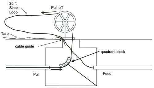
7.4.3 Slack Cable Loop
During the pulling operation, a slack loop of cable must be maintained on the pull-off side of the capstan as shown in Figure.
Intermediate Manhole Set-up
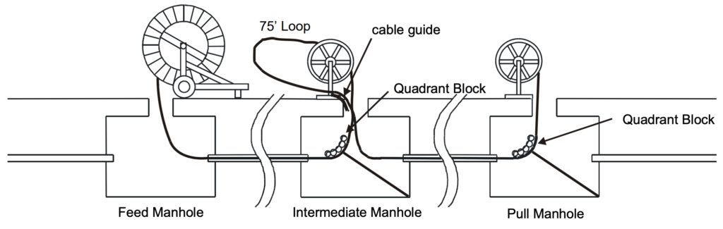
7.4.4 Adding Intermediate Capstans
If an intermediate capstan is added during the cable pull and the cable pulling eye has already passed through the manhole, a loop of slack cable must be pulled to the intermediate manhole before cable is wrapped on the capstan.
Adding an Intermediate Assist Capstan
7.4.5 Removing Cable from Intermediate Capstan Assist Winch
At the conclusion of the pull, the cable on the capstan is twist free. However, one twist per wrap will be generated in the cable if it is removed from the capstan and straightened.
8. Blown Optical Cable Installation
Cable blowing systems use high-pressure, high-velocity airflow combined with a pushing force to install the cable. A hydraulic or pneumatic powered drive wheel or drive belt is used to push the cable into the innerduct at the feed manhole. Controls and gauges on the cable blowing system allow the operator to monitor and adjust the air flow and push force that is exerted on the cable. Some cable jetting systems use a plug at the cable end to capture the compressed air and generate a small pulling force on the end of the cable.
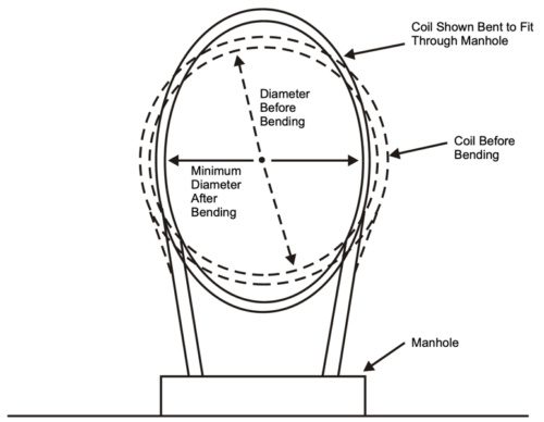
9. Optical Cable Coiling
9.1 Coils Stored at Intermediate Holes
Many end users require that coils of slack cable be stored in intermediate manholes along the cable route. These slack storage coils are used for future branch splices or route rearrangements. It is important that the coiling method accommodates the proper coil diameter and does not introduce kinking or excessive twist into the cable.
9.2 Fold-Over Method
The Fold-Over Method is recommended for storing moderate lengths of slack cable. Form a cable bight and then twist the bight to form the first cable coil. Fold the coil over to form the second cable coil.
The teardrop coiling method is recommended for storing longer lengths of cable since it is easier to roll the cable than perform repetitive folding operations. The cable is stored twist free by rolling the cable bight in a manner similar to that used on the cable end.
9.4 Garden Hose Method
The garden hose method is recommended for large diameter cables because only one turn of cable is handled at a time. The storage coil can be formed directly on the manhole racking as each additional loop is added. Each loop can be taped in place as it is added to the storage coil. This method can be used to store any length of slack cable.
9.5 Coils Stored at Splice Locations
Slack cable must be stored at splice locations to allow for splicing. Typically, a cable length of 50 to 100 feet is required for splicing purposes; however, the actual cable length may vary depending on the accessibility of the manhole.
10. Racking Fiber Optic Cable and Innerduct
Cable racking normally begins in intermediate manholes and proceeds manhole by manhole toward each end of the cable. Slack for racking the fiber optic cable may come from either the feed or the pull manhole depending on which end is closer and the amount of excess cable that is available. The preferred method of obtaining racking slack is pulling by hand. If the cable cannot be moved by hand, a split cable grip can be attached to the cable and the cable can be pulled using a cable winch or a chain hoist. Do not exceed the maximum tension rating or violate the minimum bending diameter of the cable while pulling the slack.
Cable coils should be racked in a location where they will not be damaged, preferably on the manhole wall behind in-place cables. Do not decrease the diameter of the cable coils. If slack cable must be removed from the coil for racking purposes, remove one or more loops from the coil and then enlarge the coil to absorb excess slack. Tie the coil securely in place with plastic ties.
Making an overseas phone call? Using cloud computing? If so, there’s a 99 percent chance your call or message is being carried by an undersea fiber optic cable.
Now, new research with lasers may let service providers “push” even more data through these cables to help meet the booming demand for transmission between North America and Europe. In fact, this new method could even increase network capacity without requiring new ocean cables, which can cost hundreds of millions of dollars to manufacture and install.
Setting A New Standard
A research team from Infinera has set a new efficiency standard for transatlantic fiber optic cables. Testing 16QAM modulation – a new approach to transmitting light signals — the group not only shattered efficiency records for data transfer. They nearly doubled data capacity and approached the assumed upper limit for this type of transmission.
The team managed to extend record-setting capacity across the Atlantic Ocean using the MAREA transatlantic cable. This cable spans approximately 4,104 miles (6,605 kilometers) from Virginia Beach, Virginia, to Bilbao, Spain. Partially funded by Facebook and Microsoft, MAREA now holds the record for the highest-capacity cable crossing the Atlantic Ocean.
Skyrocketing Demand
The need for new and better optical fiber and fiber optic cables has constantly grown since the first undersea trans-Atlantic cable was installed back in 1858. Because of the move to cloud-based computing, that demand has skyrocketed over the past decade.
It’s important to note that while this was the first time that PM-16QAM signals were sent over this distance, the team combined equipment readily available to the industry with high-speed lasers to make the transmission. The team generated signal speeds reaching 26.2 terabits per second, a 20 percent increase over what cable developers believed was possible.
Even More Good News
This experiment delivered results much the same as next-generation chip sets from other vendors that use a different technique called probabilistic constellation shaping (PCS). According to the research team, the good news for service providers is that the new technique can be combined with PCS for even faster speeds in the future.
The group presented their research results at OFC 2019 in San Diego.
The National Physical Laboratory (NPL) recently conducted photonics research that may lead to new quantum technologies and telecom systems. The researchers discovered unexpected qualities in light that could, in the long term, lead to completely new electronic devices and applications.
Light is frequently used in electronics involved in telecommunications and computing. One good example of this is how light is used in optical fiber. Optical fiber and fiber optic cables are used to transmit many types of communication around the world, including telephone calls and internet connections.
As mentioned in Physical Review Letters, the NPL researchers studied whether and how light can be controlled in an optical ring resonator. This resonator is a tiny device that can store extremely high light intensities. In an optical ring resonator, wavelengths of light resonate around the device. A comparison would be how some “whispers” can travel around a “whispering gallery” and be heard on the other side.
In a first-ever study, the researchers used optical ring resonators to pinpoint the interaction of two kinds of spontaneous symmetry breaking. The team displayed new ways to manipulate light by (1) studying how time varied between pulses of light and (2) how the light was polarized.
Typically, light follows what is called “time reversal symmetry.” This principle means that if time is reversed, light should return to where it started. However, in the NPL research, at high light intensities, symmetry was broken within the optical ring resonators. A lead scientist on the project noted that, when the ring resonator was seeded with short pulses, the circulating pulses inside the resonator would arrive either before or after the seed pulse. However, they would never arrive at the same time. This discovery could be potentially used to combine and rearrange optical pulses in telecommunications networks.
The researchers also learned that light can suddenly change its polarization in ring resonators. A related example would be you picking a guitar string in a vertical direction, but then having the string begin to vibrate in either a circular clockwise or counter-clockwise direction. The researchers believe that the results of these experiments will not only help to direct the development of improved optical ring resonators (such as for atomic clocks for exact time-keeping). They also feel that these findings will also help scientists to understand how they can control light in photonic circuits in sensors and in quantum technologies.
According to Pascal Del’Haye, NPL Senior Research Scientist, “Optics have become an important part of telecom networks and computing systems. Understanding how we can manipulate light in photonic circuits will help to unlock a whole host of new technologies. These include better sensors and new quantum capabilities, which will become ever more important in our everyday lives.”
Researchers at Australia’s RMIT University recently discovered a new fiber optic breakthrough that could lead to 100 times faster internet speeds. This new development detects light that has been twisted into a spiral.
According to research in Nature Communications, developers could upgrade existing fiber optic networks and boost efficiency using this discovery.
HOW IT WORKS
Fiber optic cables use pulses of light to transmit information. However, users can only store that data based on the color of the light and whether the light wave is horizontal or vertical.
The RMIT researchers twisted light into a spiral and created a third dimension for light to carry information – the level of orbital angular momentum, or spin. Dr. Min Gu of RMIT compared it to the double helix spiral of DNA. According to Dr. Gu, a greater amount of angular momentum allows an optical fiber to carry a larger amount of information.
Researchers have used “twisted light” approaches and orbital angular momentum before. They encoded a greater amount of data in various degrees of twist using these “twisted” methods. In fact, researchers at Boston University and the University of Southern California developed an optic fiber that could twist light. However, the teams used detectors as large as “the size of a dining table.” The RMIT researchers created a reasonably-sized detector that reads the information it holds. The new detector is the width of a human hair.
WHAT IT CAN DO
Providers could upgrade long haul networks around the globe with this new fiber optic technology. These companies include the NBN Co. NBN is deploying Australia’s national broadband network. The company expects to complete this network by 2020.
NBN is “prepared for future demand.” However, they have also stated that fiber optic advances such as this one by RMIT need further testing and acceptance before being deployed. A spokesperson commented, “Laboratories continually test new communications technologies for many years before they are commercialized. Equipment manufacturers and network operators must accept these new methods on a widespread scale before they are ready to be deployed in the field.”
High density cable means more fiber density in less space. From 5G to data centers to FTTx, the picture is clear. Everyone uses more bandwidth than ever before. And while bandwidth demand may seem endless, the space to install fiber optic cable isn’t. That’s why being able to install more optical fiber in the same or less space can be a game changer for today’s network operators. And it’s why “High Density” is also a critical word for many service providers today.
With microcables and rollable ribbon cables that increase fiber density while saving on space, OFS is your high-density fiber optic cable solutions provider.
Rolling In the Optical Fiber
Rollable Ribbon fiber optic cables are one of the most exciting outside plant (OSP) cabling technologies today. These cables feature rollable ribbons, the newest fiber ribbon design from OFS. This ribbon can be “rolled” (compacted) and routed like individual fibers, allowing the use of smaller closures and splice trays.
With up to 3,456 fibers, OFS AccuTube®+ Rollable Ribbon (RR) Cables help network operators double their fiber density in the same size duct or space. They also enable very efficient, cost-effective mass fusion splicing and easy individual fiber breakout. This ability helps simplify installation and save on labor costs. And by maximizing duct use, high-density AccuTube+ RR Cables are an excellent choice for connecting very large fiber distribution hubs. They are also very suitable for data centers, FTTx and access networks.
Taking Things Indoors……
With the award-winning AccuRiser™ RR and AccuFlex® RR Cables, network operators can bring the benefits of rollable ribbon cables indoors. The innovative indoor/outdoor AccuRiser RR Cable helps ease cable installation over ladder racking and through tight bends during routing. This high-density cable is excellent for use in data centers or central offices. It’s also a great choice for building-to-building cable connections along with routing for terminations and frames, and preconnectorized applications.
The strong yet flexible, plenum-rated AccuFlex RR Cable helps prevent installation problems such as packing density, routing and deployment speed. This cable’s flame rating meets NFPA 262, allowing the cable to be installed into air-handling spaces. The AccuFlex RR Cable is an outstanding solution for data centers, central offices and head ends.
With Limited Space, Go Small (and Dense)
To help solve the problem of deploying or upgrading crowded FTTx or underground networks, OFS created the high-density MiDia®Microcable family. Optimized for exceptional air-blown installation, MiDia microcables can help lower installation costs while increasing fiber optic density and capacity in limited spaces. The MiDia Cable portfolio includes MiDia Micro FX Cable, MiDia Micro GX Cable and MiDia200 Micro FX Cable.
And for network operators who prefer ribbon cables and the benefits of mass fusion splicing, OFS offers the AccuRibbon® DuctSaver® FX Cable. This cable makes optimal use of valuable duct space. It also maximizes the key advantages of air-blown microduct installation: rapid deployment and service turn-up.
To learn more about high-density fiber optic cables, contact OFS at 1-800-fiberhelp.
Detecting ocean-floor seismic activity is crucial to our understanding of the interior structure and dynamic behavior of the Earth. However, with 70% of the planet’s surface covered by water and only a handful of permanent, ocean-bottom seismometer stations, very little overall seismic activity is actually recorded.
Now, a group of researchers from the United Kingdom, Italy and Malta have found a way to use submarine fiber optic cables already deployed on the ocean floor as seismic detectors. In a paper published in the journal Science, the research group outlines how they discovered this capability and how it would operate.
Giuseppe Marra, a member of the group, was testing an underground fiber cable between two locations in the United Kingdom. Noticing a small slowdown in signal delivery, he traced it to tiny vibrations bending the light. He then determined that the vibrations were caused by a remote earthquake. This discovery inspired him to explore using fiber optic cables as seismic detectors.


 The National Physical Laboratory (NPL) recently conducted photonics research that may lead to new quantum technologies and telecom systems. The researchers discovered unexpected qualities in light that could, in the long term, lead to completely new electronic devices and applications.
 Researchers at Australia’s RMIT University recently discovered a new fiber optic breakthrough that could lead to 100 times faster
  High density cable means more fiber density in less space. From 5G to data centers to FTTx, the picture is clear. Everyone uses more bandwidth than ever before. And while bandwidth demand may seem endless, the space to install fiber optic cable isn’t. That’s why being able to install more optical fiber in the same or less space can be a game changer for today’s network operators. And it’s why “High Density” is also a critical word for many service providers today.
 Detecting ocean-floor seismic activity is crucial to our understanding of the interior structure and dynamic behavior of the Earth. However, with 70% of the planet’s surface covered by water and only a handful of permanent, ocean-bottom seismometer stations, very little overall seismic activity is actually recorded.