
WELCOME BACK, FIBER GEEKS!
As a quick refresher, article 1 in this series focused on growth in bandwidth demand. We also looked at attenuation in optical fibers caused by factors external to the fiber e.g. bending, and built in attenuation mechanisms i.e. scattering and absorption.
In this second article, we will focus on the several types of dispersion that exist in fiber.
DISPERSION – WHAT IS IT?
Much, but not all, of the traffic traveling through fiber networks takes the form of pulses of laser light. Such a pulse is created by turning a laser on and off, creating light pulses where “no light” represents a digital “0” – and “full light” represents a digital “1”. Digital information is consequently a series of “no light” and “full light” transmitted in a code which a receiver at the other end of the fiber understands and can convert to a digital electrical signal.
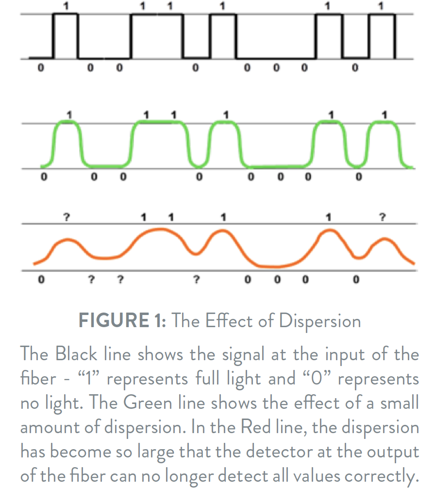
Illustrating such a signal would be a series of square pulses as shown in Figure 1.
Whenever such a signal is affected by dispersion, the edges of the square pulses will be rounded, and the pulse will be spread out over time. So dispersion broadens the pulses.
If the dispersion is small, the detector at the other end of the fiber will still be able to detect the signal correctly. Once the dispersion grows too large, the broadened pulses will overlap each other and the detector will start misreading the signal, creating errors that will effectively hamper the transmission quality. A measure of that quality is the BER (Bit Error Rate) which states the number of transmission errors relative to the total number of transmitted bits.
Since a faster transmission rate requires pulses to be of a shorter duration, this also means that a given level of dispersion will be more harmful to faster transmission rate signals. Furthermore, dispersion is almost always dependent on the fiber length – the longer the fiber, the greater the dispersion.
Hence transmission is limited by: A) The dispersion of the fiber B) The transmission rate, and C) The length of the fiber. Dispersion can be described as a “speed limiter”- and the 3 main types are:
Modal Dispersion, Chromatic Dispersion and Polarization Mode Dispersion.

Modal Dispersion is the most serious of the dispersion types, and hence the most severe “speed limiter”.
Light “modes” are different types of waves carrying the light through the fiber. In a “Multi Mode” fiber, the core is rather large and may typically allow up to 17 different modes to propagate. In a “Single Mode” fiber, the core is so small that it will allow only one mode to propagate.

The problem is that the different modes follow different paths through the fiber – and these paths are of different lengths. Some modes travel close to the center of the core – others bounce against the outer edges of the core, and these modes travel a longer way than the ones close to the center. So the different modes travel different distances – and hence some tend to travel faster than others. Parts of the light being injected into the fiber will travel via one mode – other parts via another mode – and so on. If nothing is done to mitigate this, parts of the input signal will arrive at the output later than other parts – and this will cause the output signal to be “dispersed” relative to the input signal as illustrated in Figure 1.
To try to minimize the dispersion of the signal to the output of the fiber, the fiber core of a multimode fiber is designed to delay the Light Modes travelling close to the core (which is the shortest distance) and to speed up the modes travelling the longest distance. In a perfect world this would result in all modes bringing light simultaneously to the output of the fiber. Alas the world is less than perfect, and as such a bit of Modal Dispersion cannot be avoided in real life.
This means that, even though Multimode fibers are able to use very price efficient light sources (like LEDs or VCSELs) they are still limited to transmission distances of typically less than 2 km, actually often less than a few hundred meters.
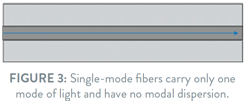
The way to avoid Modal Dispersion is to shrink the size of the fiber core. In a small fiber core there is only room for one light mode to exist, called the Fundamental Mode. In such single-mode fibers, higher order modes may indeed be generated at splices or connectors, but they will leak out of the fiber after traveling a short distance through the fiber.

Having now found a way to avoid the most important speed limiter we can turn our attention to the next in line.
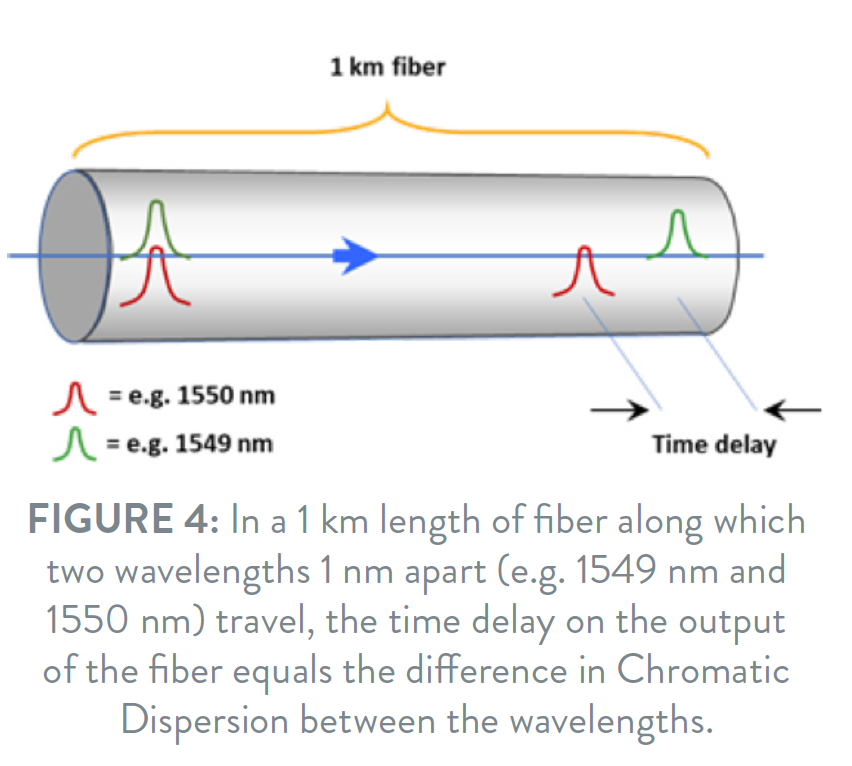
Chromatic Dispersion means that light of different wavelengths travel with different speeds along the fiber. Again, such a difference results in the “blurring” of the signal on the output side of the fiber and effectively acts as a speed limiter.
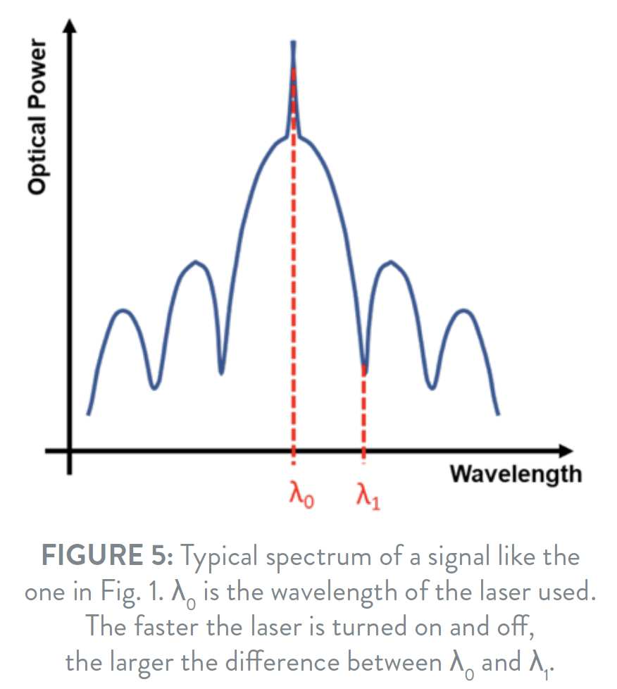
One might wonder why this should be such a problem, since lasers used to inject light into the fiber have very precisely defined and stable wavelengths. However, quickly turning a laser light on and off actually by itself generates a number of new wavelengths close to the original laser wavelength. Most of these new wavelengths are luckily quite weak and will not cause problems – but unfortunately as the laser light is turned on and off ever more quickly, the range of generated wavelengths broadens (Figure 5).
In such transmission systems the problems caused by Chromatic Dispersion worsen with increasing transmission speed and with longer fiber lengths (scaling linearly with fiber length).
Trying to minimize problems with Chromatic Dispersion the “Dispersion Shifted” (ITU-T G.653) fiber type was initially developed. In classical standard single-mode (ITU-T G.652) fibers the Chromatic Dispersion is zero around 1310 nm. The Dispersion Shifted fibers were targeted for the Chromatic Dispersion to be zero around 1550 nm, because the attenuation of the fiber is lower at 1550 nm and so this combination seemed ideal.
Basically, this worked fine right up until DWDM arrived. In DWDM systems a number of individual channels are transmitted over the same fiber. Each channel is assigned a unique wavelength, but unfortunately the fiber non-linearity called Four Wave Mixing (FWM) tends to cause unwanted noise problems in DWDM systems if the Chromatic Dispersion in the fiber is very low.
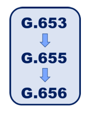
So realizing that some level of Chromatic Dispersion is preferable in order to limit fiber non-linearity problems in DWDM systems, Non-Zero Dispersion Shifted fiber (ITU-T G.655) was developed. This fiber type has a small amount of Chromatic Dispersion around 1550 nm (significantly smaller than standard G.652 fibers) so the “speed limitation” is smaller – but still the Chromatic Dispersion is high enough to reduce non-linearity problems very significantly. Later the G.656 Non- Zero Dispersion Shifted fibers were developed as a response to the demand for an increasing number of channels in DWDM systems. When the number of channels go up, the individual channels need to be packed more closely together – and that in turn requires more Chromatic Dispersion in the fiber to reduce the effect of the Four Wave Mixing.
In parallel with the development of new fiber types with different Chromatic Dispersion characteristics, special devices with negative Chromatic Dispersion were developed. Since transmission fibers normally have positive Chromatic Dispersion, a combination of those two can be used to reduce total Chromatic Dispersion for a full fiber link to almost zero.
With the ability to reduce the total chromatic dispersion of a transmission link, the higher Chromatic Dispersion of the G.656 fibers was consequently an acceptable technical compromise – leaving only cost issues still to be considered.
In many of the recent high-capacity transmission systems, the Chromatic Dispersion of the transmission fiber is compensated electronically with high efficiency, and for such systems fibers with high Chromatic Dispersion may actually be advantageous because it helps to limit fiber non-linearities.

Just to make confusion complete, a single-mode fiber will actually be able to carry TWO versions of the fundamental light mode. The reason for this is that light may exist in two different polarizations, the modes of which are perpendicular to one another. The phenomenon is known from some sunglasses which cut away one of those polarization modes. Reflected sunlight from the sea surface or a wet road will predominantly consist of light in one of these polarization modes – whereas light reflected by other objects will consist of a mixture of the two polarization modes. Cutting away the polarization mode of the reflected light will “kill” the reflections, but let the other polarization mode pass through the glasses, leaving other objects visible.
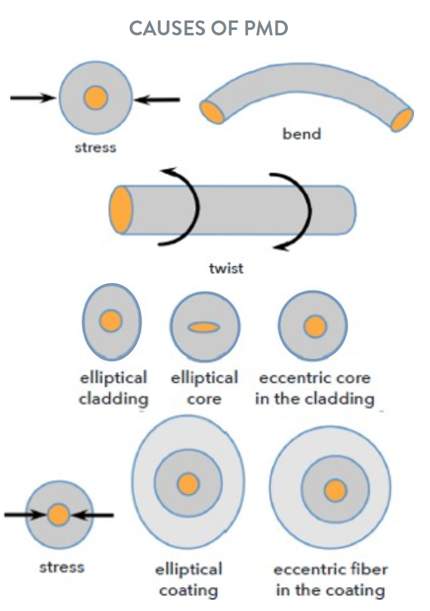
In an optical fiber, the two polarization modes will both exist, but may travel at different speeds through the fiber. Such speed-differences will arise if the fiber core is not perfectly circular and if stress is present in the fiber. Stress can be “frozen” into the fiber during manufacturing if the fiber geometry is not absolutely perfect, for example, if the cladding or coating is not circular, or if the center of the core is different from the center of the cladding or coating.
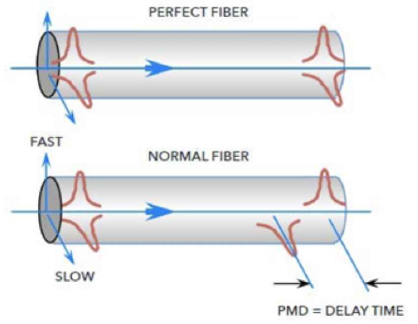
Even using state of the art, high-quality manufacturing process, the fiber will not be geometrically 100% perfect, hence there will be a speed-difference between the two polarization modes, dispersion will result, and it may limit high speed transmission through the fiber. Even if the fiber were 100% perfect, the slight bending of the fiber in a cable would introduce stress in the fiber – creating PMD. So this is our third speed limiter.
Looking at a fiber from a “PMD-perspective” it may be thought of as having a “fast” and a “slow” lane. An effective way of reducing PMD is by twisting the fiber back and forth during manufacturing so that a high number of shifts between the “fast” and “slow” lanes are effectively seen by the light travelling through the fiber.
Because stress is an important cause of PMD, externally applied stress will also affect fiber PMD. In reality just holding a fiber between two fingers may change PMD. As a result, the PMD of a fiber may be affected both by the cabling of the fiber and by external stresses, for example vibrations from a nearby railroad.
As with other dispersion types the effect of PMD increases with increased transmission distance (PMD scales with the square root of the distance) and increased transmission speed. For transmission rates of 2.5 Gbps and smaller, PMD is normally not a problem. For very high transmission rate systems, the compensation of PMD is today made electronically and built into the transmission system.
Tags: chromatic dispersion, dispersion, modal dispersion, optical fiber, PMD