
The fiber optic cable world has come a long way over the past 30 years. Products have become more rugged and user friendly, making it easier for people to enter the industry and work handling optical fiber and cable. While this is great for the industry, many people may understand the “how to” but not necessarily the “why” of fiber optics. To understand the “why” behind fiber and cable products, the next step is to become a full-fledged “fiber geek.” Because the industry changes so quickly, this is an ongoing process. The purpose behind this series of articles is to enable the reader to understand some secondary fiber specifications and their importance to the network.
Once fiber is deployed, it’s very expensive to replace. For this reason, the fiber that’s installed should be capable of withstanding multiple generations of hardware while also having plenty of room for additional wavelength growth.
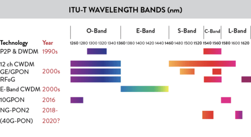
The graphic on the right highlights how wavelength usage has grown over the past three decades. For the first 30 years, applications were focused in the 1310 nm and 1550 nm regions. Given the explosive demand for bandwidth (even more so since COVID-19), it’s reasonable to assume that the next 30 years will require many more wavelengths, with potential applications across the entire optical spectrum.
The demand for bandwidth is expected to continue far into the future, driven in part by requirements for breakthrough applications such as higher resolution video, virtual reality and other applications. We expect this demand to continue to drive the need for optical spectrum provided by fiber. Fiber recommendations such as ITU-T G.652 and ITU-T G.657, are very important for network designers in setting minimum performance levels, but can ultimately be insufficient to meet the requirements for future networks. For this reason, performance beyond the standards can be very important.

This article will focus on critical optical parameters starting with attenuation, or loss in the fiber. Attenuation is a very important optical parameter, and there are many aspects to it. Additional articles in this series will focus on other optical parameters, including chromatic and polarization mode dispersion, splice loss, and an introduction to non-linear effects.
Keeping a low fiber attenuation has always been a focal point in fiber development – and today even more so with the widespread use of Coherent Transmission systems. These require large core and ultra-low loss attenuation fibers (typically ITU-T G.654 fiber types) for optimal performance of 100G and faster transmission systems.
Attenuation is typically measured in terms of optical dB. It is a logarithmic measurement where the Loss of a fiber equals 10*log (“Power at the- input side of the fiber” / “Power at the output side of the fiber”). Basically every 3 dB of loss corresponds to the optical power being cut in half. It is fair to assume, that the attenuation of a fiber is almost constant over the length of the fiber. So if a fiber loss is 0.25 dB/km, a total loss of 3 dB will be reached after 12 km of fiber has been passed by the optical signal in the fiber.
Looking at the different loss mechanisms in fibers, it may be helpful to distinguish between:
A): Attenuation caused by factors external to the fiber (as for example bending), and
B): Built in attenuation mechanisms.
Looking at B) first, there are two main loss mechanisms in optical fibers: Scattering and Absorption.
SCATTERING
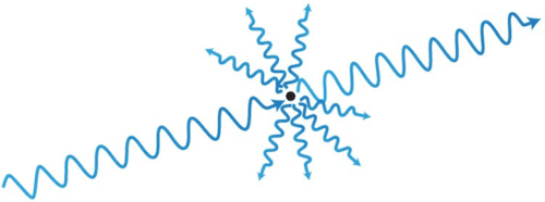
Also called “Rayleigh scattering”, even the best and purest, synthetic quartz glass (of which OFS fibers are made) is not 100% homogeneous. They consequently contain small fluctuations of glass density, which are frozen into the glass during manufacturing and may scatter the light when hit by a light ray (this is the same mechanism responsible for the blue color of the sky, when sunlight scatters off molecules in the atmosphere). Much of the light will continue traveling in the original direction, but a small part of the light will be scattered in all directions. Some light will propagate sideways out of the fiber, where – for transmission purposes – it will be lost. Some of it will actually be scattered backwards towards the sender. This is the phenomenon used by OTDR measurement devices to measure fiber attenuation, so the device only needs to be connected to one end of the fiber.
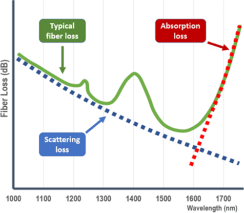
In optical fibers scattering is dominant at shorter wavelengths whereas the opposite is true for the other built in attenuation mechanism: Absorption (Figure 4).
ABSORPTION
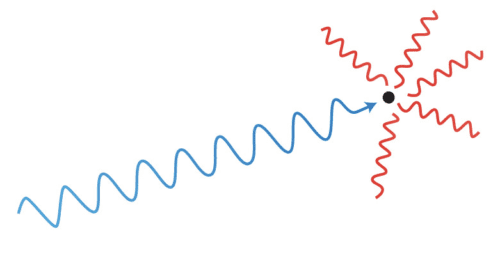
Basically absorption happens when a light ray hits something – and gets converted into heat. So for practical purposes the light simply “disappears”.
Even extremely small impurities – down to a fraction of a micron – may absorb light, causing unwanted attenuation. It may be small particles – but it may also be impurities in the raw materials used for fiber manufacturing. This is why such extremely close attention is paid to the quality and purity of the raw materials used.
Due to the inherent material structure of glass, Absorption increases rather drastically at wavelengths longer than approximately 1550 nm (Figure 4)
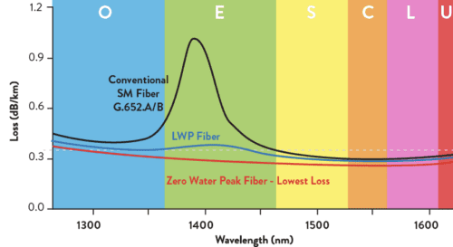
Of particular interest over the years has been the hydroxyl (OH-) ion, which absorbs light around 1383 nm, giving rise to the so-called “water-peak” in the attenuation curve for the fiber (figure 5 – black curve). Being a by-product of the actual manufacturing process, it is difficult to fully avoid the presence of hydroxyl ions in the fiber, but it is possible to pacify the attenuation increase at the wavelengths close to 1383 nm. This is done by adding deuterium gas which interacts with the free bond of the hydroxyl ion thereby acting as a barrier securing excellent long-term Water Peak attenuation performance.
Conventional single-mode fibers meeting the G.652 recommendation may have a high Water Peak loss. This could limit the use of the fiber in some applications and may also make the fiber less useful in transmission systems using modern Raman amplification, where amplifier laser-pumps would typically operate 110 nm below the transmission signal wavelength.
OFS have fibers classified as Zero Water Peak (ZWP) with even better specified Water Peak performance than the so-called Low Water Peak (LWP) fibers. The long-term stability of ZWP fibers is excellent whereas for some types of ITU-T G.652 fibers the water peak attenuation might actually increase over their lifetime, slowly reducing the quality of the network.
Because of the optimized Water Peak performance, ZWP fibers serve the widest ranges of wavelengths and support the highest number of applications, as illustrated in Figure 1.
Figure 5 shows three different grades of ITU-T G.652 fiber, and how they may be performing in the water peak region around 1383 nm.
For the most part, scattering and absorption properties are locked into the fiber during manufacturing.
Bending, however, is another story…
BENDING
Bending is a very important mechanism. As briefly mentioned, it is caused by factors external to the fiber and so both the cabling process and installation in the field can affect attenuation caused by bending.
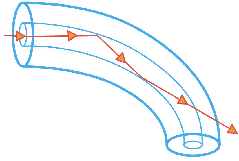
To put it simply, what makes an optical fiber work is the use of different types of glass for the fiber core and for the glass surrounding the core (also known as the cladding). In this way, a sort of a tubular mirror surrounding the core is created. This is what keeps the light inside the fiber, using the concept of “total internal reflection” to guide the light. However, this mirror is not a perfect one. It only works if the light rays in the fiber run almost parallel to the core, and so if the fiber is bent (too) tightly (i.e. past the “critical angle” when reflection turns to refraction), light will leak out of the fiber causing loss – or attenuation.
This is called macro bending, where the diameter of the bending is larger than a few millimeters, which is what one would intuitively understand as “bending” the fiber.
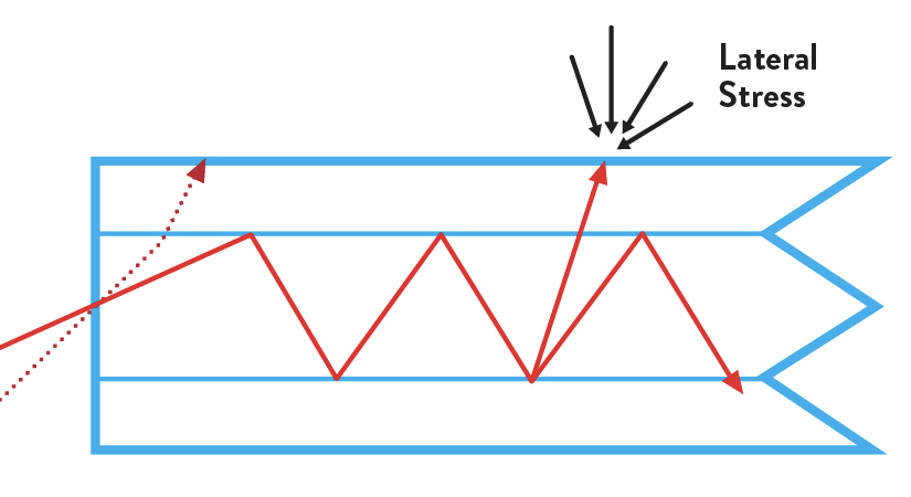
Another type of bending is called micro bending. It concerns bending diameters smaller than 1 mm and could happen – as an example – if a fiber is squeezed between two sheets of sandpaper. Much more relevantly it may also happen if the fiber is being squeezed inside the cable construction (for example by the tubes containing the fibers) creating stress on the fiber. As loads/stresses increase, so does the loss.
Both types of bending loss cause attenuation increase, but it is possible to tell the two types of bending apart by considering the added loss at different wavelengths as illustrated in Figure 8.
Macrobending losses tend to be small at short wavelengths, but may increase rather dramatically at longer wavelengths.
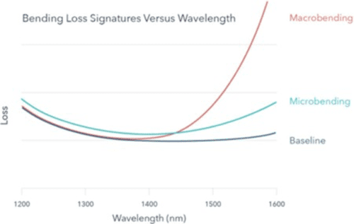
Microbending losses are also typically present at short wavelengths, but the loss increase tends to be smaller than for macrobending at the longer wavelengths.
All of the trends in fiber deployment point to the increased importance of fiber bending performance.
Service providers constantly want to put more fibers into a smaller space which means that while buffer tube diameters keep shrinking, the fiber counts used in these buffer tubes keep increasing. This leads to a situation where there is less room for fibers to move before touching a buffer tube wall, thereby increasing the risk of microbends.
In addition, service providers primarily installed cables in either the outside plant, the inside of central offices, or into remote cabinets. Everywhere great care was taken to avoid small diameter bending. However, today’s fiber is going to places where it hasn’t gone before. It’s going inside our homes and businesses and also up poles and onto rooftops to feed cellular and Wi-Fi sites.
Tolerance to bending will be even more important in the future.
Micro and macro bends affect the network in ways that are not always obvious.
Bend-related losses are sometimes experienced in cold temperature environments. For this reason, fibers and cables should always be tested under low temperature conditions. As a network designer, it’s always a good idea to account for at least some optical margin for small potential attenuation increases in cold temperatures.
loss fibers already now.
Especially very high-density designs may benefit from using bend insensitive fibers due to the unavoidable bends and lack of free space for fiber movement in the cable design itself.
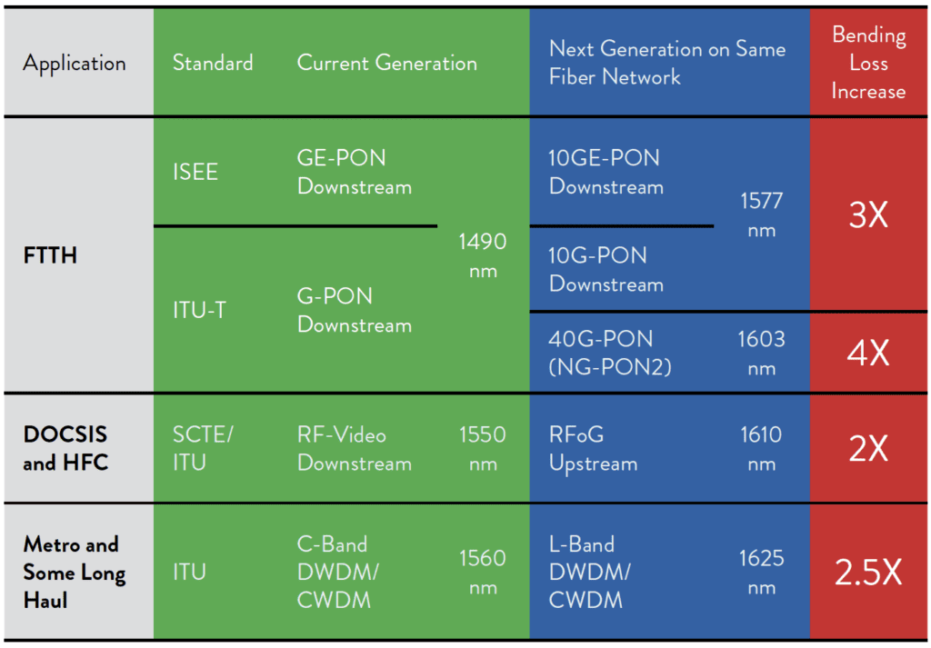
While these issues are already important today, they will become even more important tomorrow. The reason is that next generation optical transmission protocols may typically use longer wavelengths than the existing protocols.
As highlighted earlier, longer wavelengths will often result in higher bending loss. Theoretically, a GPON network operating flawlessly today at 1490 nm – containing inadvertent bends – could have its reach reduced by almost half when it is upgraded to NG-PON2, operating at 1603 nm.
So a FTTH network installed today and working fine may not be suited for operation with future generation transmission equipment.
HELP IS ON THE WAY
In order to enable more compact cable constructions and allow for easier installation and perhaps even allow for the use of less experienced craftspeople for cable installation, quite a bit of attention has recently been focused on developing fibers with reduced sensitivity to bending i.e. those defined by the ITU-T Recommendation G.657.
G.657 specifies 4 different classes of fibers: “A1”, “A2”, “B2” and “B3”.
The “A” fibers are required to also fulfill (or to comply with) the specifications of the ITU-T G.652.D recommendation, whereas the “B” fibers may deviate from G.652.D on some parameters. The numbers (1, 2 or 3) signifies the fibers tolerance to bending – B3 fibers being most bending tolerant. Many “B3” fibers do today comply with G.652.D and should rightfully be labelled: “A3”, but such a class is not specified by ITU-T.
ITU-T G.657.A1 fibers are the closest to standard G.652.D fibers and may soon be the primary choice for the vast majority of fiber networks. OFS has combined G.657. A1 and G.652.D performance with a 9.2-micron mode field diameter.
G.657.A1 fibers with 9.2-micron mode field diameter perform the same way as standard G.652 fibers in terms of splicing – and can consequently be said to splice “seamlessly” to the huge base of already installed fibers. By offering the same splice performance as standard G.652 fibers, installation crews and quality inspectors will notice no change in performance and hence be given no cause for concern – even
though the advantages of better tolerance to bending will still be there.
These fibers are ideal for most of today’s typical short-distance (<1000 km) and low data rate (<400Gbps) applications, including standard outside plant (OSP) loose tube, ribbon, rollable ribbon, microduct cables, and drop cables.
ITU-T G.657.A2 fibers can be bent more tightly with lower loss. They are most commonly used in central office and cabinet environments, such as Fiber Distribution Hubs (FDH). These fibers are also commonly used in building backbone networks and as tails for various pre-terminated panels and other devices. In these environments, the fibers may need to be bent more tightly than in typical OSP cable applications.
The application spaces just mentioned for A1 and A2 fibers would typically involve one fiber to carry traffic for thousands of customers, meaning that a fiber break would affect the service to thousands of users. Here reliability is consequently paramount. In such situations A2 fibers (and A1 as well) offer the advantage of providing an “early warning” signal of increased attenuation whenever they are bent tightly enough to potentially cause reliability concerns. This is especially important for central office applications where one fiber could provide the feed for millions of customers.
ITU-T G.657.B3 fibers are the third main category of bend insensitive fibers. These fibers are designed and recommended for use in the drop portion of a Fiber-to-the- Home (FTTH) network serving a few customers per fiber. Homes and buildings with lots of tight spaces are very demanding places to deploy fiber. For optimized performance in such applications OFS has fiber which is designed and specified for use with bending radii as low as 2.5 mm which is significantly less than the minimum bending radius of 5 mm specified in the G.657.B3 recommendation.
OFS has fibers used in cables with a diameter of only 0.6 mm, enabling almost invisible in-house cable routing with a minimum of bending management. This avoids bulky and distasteful installation in private homes. For more demanding deployments, ruggedized cable designs with a diameter of 4.8 or 3mm may even be routed around corners and stapled using fast and easy installation practices, with negligible signal loss.
G.657 fibers which are not compliant with G.652.D are often assumed to have very small cores giving rise to significant additional splice losses when spliced to standard G.652.D fibers. However, that is not necessarily so. It is possible to get G.657.B3 fibers specified with an ultra-low bending radii of 2.5 mm and – whereas these fibers are not “seamless” fibers – they do in fact comply with the G.652.D recommendation in terms of core size. The only thing preventing such fibers from complying with G.652.D is the Chromatic Dispersion, and since they are primarily intended for in-building applications, the length will typically be much less than the 10 – 40 km fiber length in which the higher Chromatic Dispersion may typically start presenting problems.
Regarding bending loss however, the performance of such a fiber is significantly better. The loss for a single turn of 2.5 mm radius at 1550 nm for such a fiber is max. 0.2 dB – whereas the similar loss for a standard G.652.D fiber exceeds 30 dB.
Tags: absorption, attenuation, optical fiber, scattering